
Strategy for fueling a diesel engine

Active Publication Date: 2017-05-02
INT ENGINE INTPROP CO LLC
View PDF18 Cites 0 Cited by
  • Summary
  • Abstract
  • Description
  • Claims
  • Application Information

AI Technical Summary

Benefits of technology

The patent describes a method of injecting fuel into an engine during two phases. The first phase injects fuel at maximum speed and then reduces it in the second phase. This results in a more uniform mixture of fuel and air in the engine chamber before combustion occurs. This method reduces the amount of soot and nitrogen oxides generated during combustion.

Problems solved by technology

However, if the response time of the sensor and the processing time of the control algorithm are not sufficiently fast, the data obtained during the immediately preceding engine cycle can be used.

Method used


Image

  • Strategy for fueling a diesel engine
  • Strategy for fueling a diesel engine

Examples


Embodiment Construction

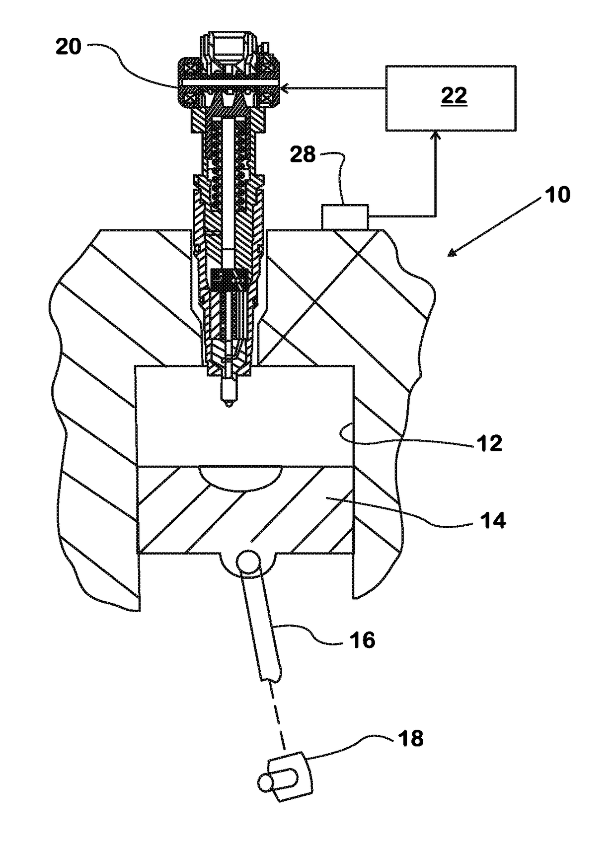
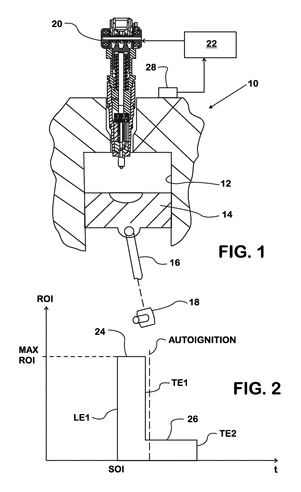
[0017]FIG. 1 shows a portion of a diesel engine 10 comprising an engine cylinder 12 within which an engine piston 14 coupled by a piston rod 16 to a crankshaft 18 reciprocates. A fuel injector 20 injects diesel fuel directly into engine cylinder 12 where the fuel combusts in air that has been compressed by engine piston 14 to create pressure that forces the piston to downstroke and impart torque to crankshaft 18 through piston rod 16.

[0018]Fuel injector 20 is representative of ones that are capable of injecting fuel at maximum injection pressures of at least 3,000 bar. At maximum injection pressure, fuel injector 20 delivers maximum ROI. Fuel injector 20 is also capable of injecting fuel at significantly lower pressures that result in smaller ROI. Operation of fuel injector 20 is controlled by a processor-based engine controller 22 that has a control algorithm which processes various data according to a control strategy to control timing and duration of fuel injections by fuel injec...


PUM


Abstract

A compression ignition engine (10) operates to fuel an engine cylinder (12) to create an in-cylinder air-fuel charge and to cause that charge to autoignite. A fuel injector (20) operates to inject fuel into the engine cylinder for substantially the entire duration of a first phase (24) of fuel injection at substantially the maximum injection pressure that the fuel injector can deliver to create a premixed fraction of the in-cylinder air-fuel charge prior to autoignition. As the first phase ends, fuel injection transitions to a second phase (26) which commences in advance of autoignition. During the second phase, the fuel injector injects fuel into the engine cylinder at a rate of injection that is significantly less than the rate of injection used during the first phase.

Description

FIELD OF THE DISCLOSURE[0001]This disclosure relates to a strategy for fueling a compression ignition (diesel) internal combustion engine. More specifically it relates to a strategy for more completely combusting fuel in an engine cylinder so that smaller quantities of soot and NOx are present in exhaust leaving the engine cylinder.BACKGROUND[0002]Premixed Charge Compression Ignition (PCCI) is a known process for fueling a diesel engine in a manner that creates an air-fuel charge inside an engine cylinder during a compression upstroke of a piston during an engine cycle. After a desired quantity of fuel for the charge has been injected into the cylinder, the increasing compression of the charge by the upstroking piston creates sufficiently large pressure to cause auto-ignition of the charge as the piston is coming to top dead center (TDC). Auto-ignition may occur as the substantially simultaneous spontaneous combustion of vaporized fuel at various locations within the mixture.[0003]W...

Claims


Application Information

Patent Timeline
Patent Type & Authority Patents(United States)
IPC IPC(8): F02D41/30F02D41/40
CPCF02D41/30F02D41/401F02D2200/0618F02D2250/31Y02T10/44Y02T10/40
Inventor EL-BESHBEESHY, MAHMOUD S.SIUCHTA, GRZEGORZ
Owner INT ENGINE INTPROP CO LLC
Learn More