Eureka AIR delivers breakthrough ideas for toughest innovation challenges, trusted by R&D personnel around the world.

Method for combusting exhaust gas with oxygen feed line

a technology of exhaust gas and oxygen feed line, which is applied in the direction of combustion types, lighting and heating apparatus, incinerator apparatus, etc., can solve the problems of no longer usable exhaust gas during the conversion process of materials, and achieve the effect of reducing the vulnerability of the flaring system to failures

Inactive Publication Date: 2016-03-17
LINDE AG
View PDF11 Cites 0 Cited by
  • Summary
  • Abstract
  • Description
  • Claims
  • Application Information

AI Technical Summary

Benefits of technology

[0012]In the invention, an oxygen-containing gas with an oxygen content exceeding 22% is introduced into the exhaust gas, so that enough oxygen is available inside the flame, and the exhaust gases are combusted more efficiently and completely, and without soot.
[0014]Preferably used in the method according to the invention is an oxygen-containing gas, in particular oxygen-enriched air with an oxygen content exceeding 30% v / v, exceeding 50% v / v, exceeding 80% v / v, or technically pure oxygen with an oxygen content exceeding 95% v / v or exceeding 99% v / v, so that the exhaust gas reacts more efficiently with the oxygen, and a complete combustion takes place. Supplying the oxygen improves the combustion of the carbon compounds present in the exhaust gas. The advantage to this is that less soot is formed, and nitric oxides in the exhaust gas are also reduced.
[0016]In the method according to the invention, the oxygen-containing gas is further relayed through a nozzle and brought inside the flame, preferably at a higher speed that preferably measures 0.1 to 3 times the speed of sound, especially preferably 0.5 to 2 times, most especially preferably 0.8 to 1.2 times the speed of sound. The speed is determined using the nozzle cross section and supply pressure, adjusted via the upstream pressure during startup, and set prior to installation of the system. As the speed increases, more ambient air is also drawn in, and thus more oxygen is guided into the inner core of the flame, thereby improving exhaust gas combustion. Injecting the oxygen-containing gas into the combustion zone generates turbulences in the flame, so that the air is mixed with the exhaust gas for smokeless combustion.
[0019]The oxygen feed line is preferably used during operational malfunctions when not enough or no steam is generated, e.g., given a nonvolatile lockout caused by an operational breakdown or unforeseen shutdown of the chemical plant. The exhaust gases can then also be combusted efficiently and without soot even without supplying steam.
[0026]To reduce the vulnerability of the flaring system to failures, the supplied quantity of oxygen is also often not regulated with a control valve, and the maximum quantity of oxygen available is always used.

Problems solved by technology

For example, the exhaust gases arise during a material conversion process or are no longer usable gaseous waste products, e.g., from internal combustion engines or technical incinerators.

Method used


Image

  • Method for combusting exhaust gas with oxygen feed line
  • Method for combusting exhaust gas with oxygen feed line
  • Method for combusting exhaust gas with oxygen feed line

Examples


Embodiment Construction

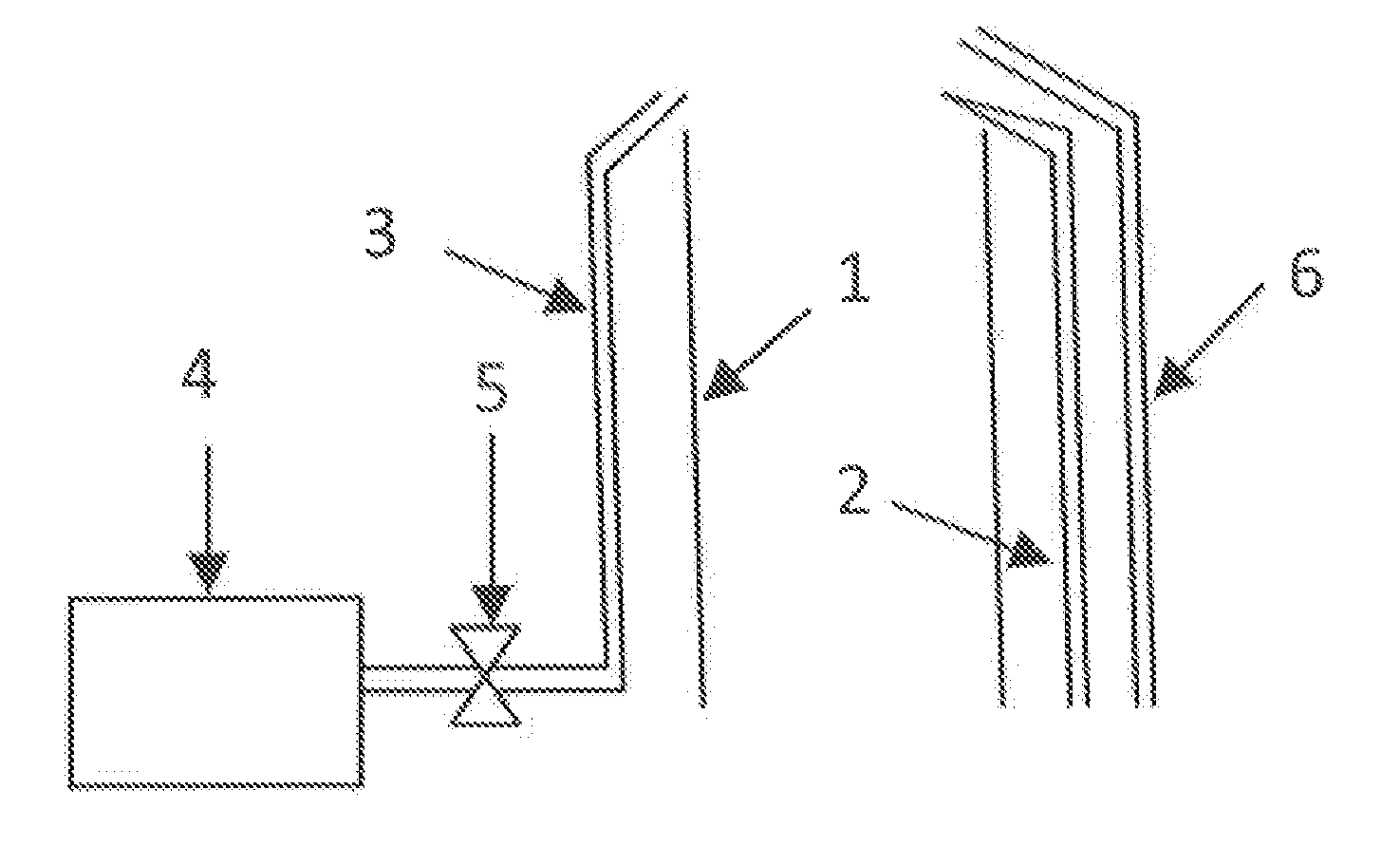
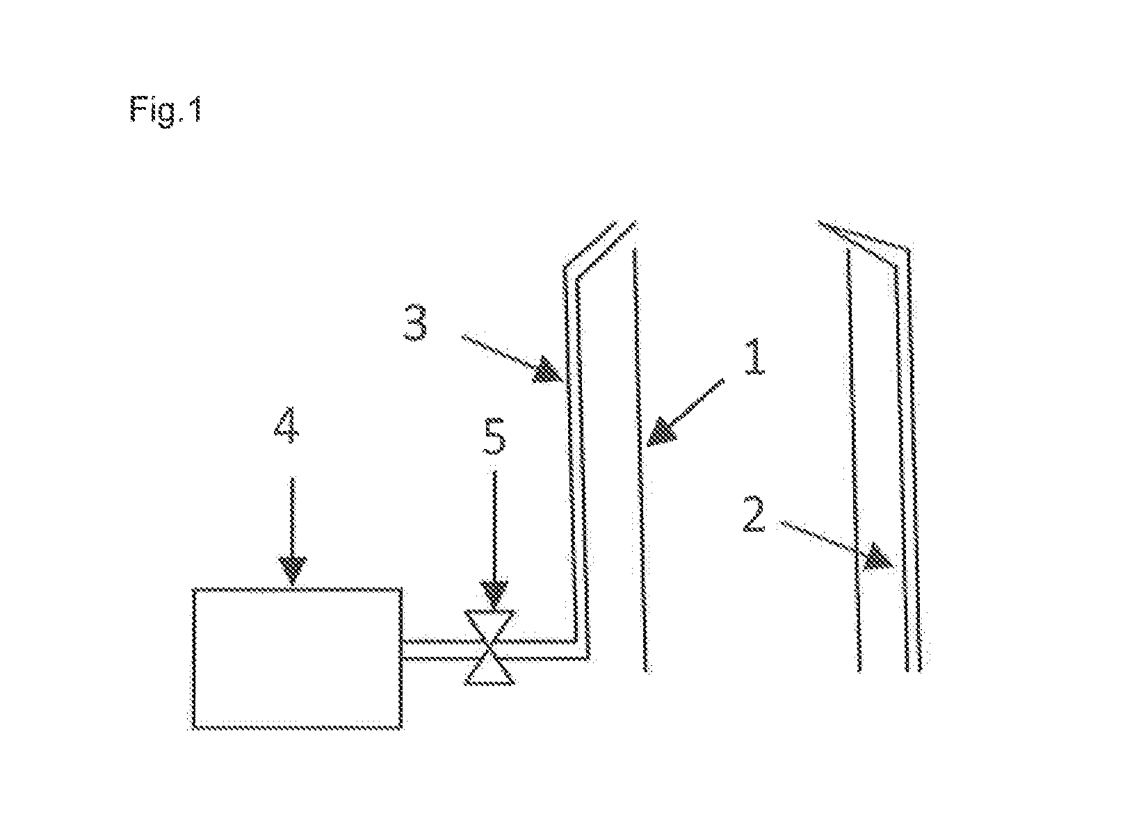
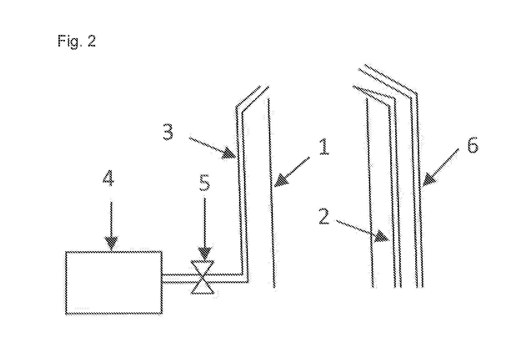
[0031]FIG. 1 presents a schematic view of a device according to the invention for combusting exhaust gases. The device consists of an exhaust pipe 1, an ignition device 2 and an oxygen feed line 3, which is connected with an oxygen tank 4. The exhaust gases, for example which come about in a refinery or in a chemical factory, exit from the exhaust pipe 1, and are ignited by the ignition device 2 with the formation of a flame.

[0032]An oxygen-containing gas, in particular oxygen-enriched air with an oxygen content exceeding 30% v / v, exceeding 50% v / v, exceeding 80% v / v or technically pure oxygen with an oxygen content exceeding 95% v / v or exceeding 99% v / v, is introduced into the flame through the oxygen line 3, wherein the oxygen is introduced from a liquid oxygen tank 4 by way of a valve 5. The valve 5 is used to release the fixed quantity of oxygen, and is designed as a shutoff valve. In addition, it is easier to provide oxygen in a tank system than to generate steam, in particular...


PUM


Abstract

The exhaust gases stemming from an oil conveyance such as in a refinery or a chemical factory are flared with oxygen-containing gas fed into the flame, in particular with oxygen-enriched air with a high oxygen content or technically pure oxygen, so as to achieve as soot-free a combustion as possible that also generates less environmentally harmful emissions. The device for combusting exhaust gases is a combination of an exhaust gas pipe, an ignition device and an oxygen line, which is connected with an oxygen tank. The oxygen feed line is used in particular during operational malfunctions instead of a steam feed line or as an additional feed line when not enough steam is generated by the chemical plants.

Description

CROSS REFERENCE TO RELATED APPLICATIONS[0001]This application claims priority from German Patent Application DE102014013474.1 filed on Sep. 11, 2014 and European Patent Application EP 14003811.8 filed on Nov. 12, 2014.BACKGROUND OF THE INVENTION[0002]The invention relates to a method for combusting exhaust gases exiting from an exhaust pipe, wherein the exhaust gases are combusted with the formation of a flame at the outlet end of the exhaust pipe, as well as to an exhaust gas combustion device, which encompasses an exhaust pipe with an outlet end for the exhaust gas along as well as an oxygen feed line connected with an oxygen tank and an ignition device.[0003]The combustion of exhaust gases is also referred to as flaring. Flaring is often used at refineries and in the chemical industry to eliminate exhaust gases that arise in particular during startup and shutdown operations and in pressure relief and evacuation equipment. Large quantities of gas can also exit in the event of malf...

Claims


Application Information

Patent Timeline
Patent Type & Authority Applications(United States)
IPC IPC(8): F23L7/00F23G7/08
CPCF23G7/085F23L7/007F23L7/005Y02E20/34
Inventor GOLDBACH, JOACHIM
Owner LINDE AG
Why Eureka
Eureka Blog
Learn More