DC level detection circuit between high speed signal line connecting ports, a system including the circuit, and methods of making and using the same

a detection circuit and high-speed signal technology, applied in the field of communication, can solve the problems of hardware unavailable, affecting the installation and use of the module, and affecting the detection accuracy of the plug-in type module, so as to increase the installation accuracy of plug-in type modules and compatibility, and expand the functionality of the high-speed signal line connection por

Active Publication Date: 2017-05-02
SOURCE PHOTONICS CHENGDU
View PDF10 Cites 0 Cited by
  • Summary
  • Abstract
  • Description
  • Claims
  • Application Information

AI Technical Summary

Benefits of technology

[0021]Relative to the prior art, the present invention has advantageous effects, including providing a DC level detection circuit and a system including the same that achieves multiplexing of one or more high speed signal line ports, thereby providing both high speed signal transmission and a hardware connection detection function. Electrical level and / or connection status detection can be achieved by adding a resistor to each port of a high speed signal line (e.g., between a plug-in module and a corresponding port), separately having a terminal thereof connected to ground and a DC voltage source (e.g., VCC), and a signal detection circuit or port connected to a resistor having a resistance much greater than that of the other resistor. When both ports of the high speed signal line are connected, the interface of the high speed signal line (e.g., of or between the signal ports) and the two resistors form a bleeder circuit. The signal level or connection status detected by the signal detection circuit or port changes from high to low, thereby determining the connection status of the high speed signal line from the electrical level at the signal detection circuit or port. The present invention can be utilized to detect the connection status of the high speed signal line and / or between a plug-in type module and a corresponding main board slot.
[0022]In addition, the third resistor and the capacitor in the low pass filter may be configured to filter high speed signals and / or prevent crosstalk, thereby increasing detection accuracy. The present circuit can provide high speed signal port (function) multiplexing and increase the installation accuracy of plug-in type modules and compatibility of modules including a main board. The above-mentioned electrical connection detection functionality can be added to substantially all high speed signal line connecting ports without adverse or negative effects on high speed signal transmission. As a result, the present invention expands the functionality of high speed signal line connecting ports, and the connection status between high speed signal lines and ports on corresponding modules can be reliably detected. Therefore, the present invention has broad application.

Problems solved by technology

However, determining whether a module is properly plugged in using a voltage in the detection port can have an adverse effect on installation and usage of the module.
This issue can be rather serious when two or more modules having the same function are integrated.
Otherwise, the hardware is unavailable, and reconnection is required.
In such a configuration, determining whether a CSFP module is properly plugged into a client-side main board based on the detected electrical level status is no longer appropriate.
Furthermore, single channel CSFP modules have no original detection port that can make the module hot-pluggable.
However, with recent developments in module utilization, there is a possibility of the MOD-ABS port being occupied.

Method used


Image

  • DC level detection circuit between high speed signal line connecting ports, a system including the circuit, and methods of making and using the same
  • DC level detection circuit between high speed signal line connecting ports, a system including the circuit, and methods of making and using the same
  • DC level detection circuit between high speed signal line connecting ports, a system including the circuit, and methods of making and using the same

Examples


second exemplary embodiment

[0057]A Second Exemplary Embodiment

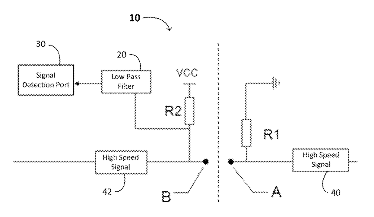
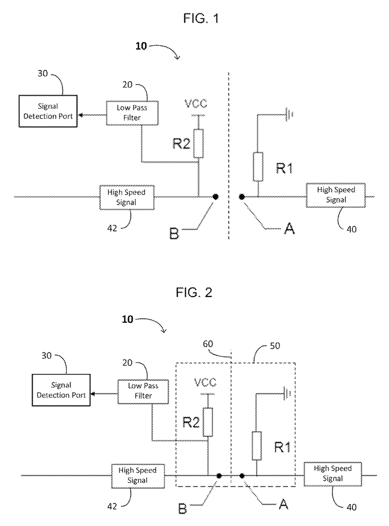
[0058]As shown in FIG. 5, a DC level detection circuit 300 between high speed signal line connecting ports A and B comprises a first resistor R1, a second resistor R2, a low pass filter 320, and a signal detection port 330. One end or terminal of the first resistor R1 is connected to the second port B of a high speed signal line 342, and another end or terminal of the first resistor R1 is grounded. One end or terminal of the second resistor R2 is connected to the first port A of the high speed signal line 340, and another end or terminal of the second resistor R2 is connected to a DC voltage source VCC. The low pass filter 320 is connected (e.g., at its output) to the signal detection port 330, and another terminal (e.g., an input) of low pass filter 320 is connected to the first port A of the high speed signal line 340. The resistance of the second resistor R2 is equal to or greater than 5 or 6 times the resistance of the first resistor R1. The el...


PUM


Abstract

A DC level detection circuit between high speed signal line connecting ports and a system using the same in optical communications is disclosed. Corresponding ports of a high speed signal line each have an additional resistor, where one additional resistor has a resistance significantly greater than that of the other resistor. The smaller resistor is grounded. The larger resistor is connected to a DC voltage source, a low pass filter, and a signal detection port. Thus, when both ports of the high speed signal line are connected, a status of the electrical level detected at the signal detection port changes. The circuit detects the connection state of the high speed signal line without negative effects on signal transmission and is applicable to various circuits, especially plug-in modules and corresponding slots. Thus, the circuit further enables signal port multifunctionality, increases module installation accuracy, and provides higher compatibility for plug-in modules.

Description

FIELD OF THE INVENTION[0001]The present invention relates to the field of communication, especially to the field of hardware detection in optical communication devices. More specifically, embodiments of the present invention pertain to circuits and methods for detecting a connection status between a plug-in module and a corresponding slot using a port for a signal line.DISCUSSION OF THE BACKGROUND[0002]At present, to simplify assembling and disassembly, slot interfaces are broadly applied to plug-in type modules and main boards in electrical communication. The interface of a plug-in type module employs one or more plugs corresponding to one or more slots, one of which is known as a “golden finger.” A “golden finger” refers to the contact segment of a slot that includes a plurality of conductive metal (typically gold) contacts. These contacts may be arranged as and / or have the appearance of fingers, so they are known as “golden fingers.” Golden fingers have a high conductivity and ar...

Claims


Application Information

Patent Timeline
Patent Type & Authority Patents(United States)
IPC IPC(8): G01R23/20G01R31/04H01L21/00
CPCG01R31/045G06F2101/00H01L21/00H01L2221/00G01R31/69
Inventor CAI, SHENGZHIWEI, QIUMINGHUANG, YUANJUNXU, YUANZHONG
Owner SOURCE PHOTONICS CHENGDU
Why Eureka
Try Eureka