N-wire two-level digital interface

a digital interface and receiver technology, applied in the field of n-wire digital interface receivers, can solve the problems of inter-symbolic interference, difficult physical implementation, phase locked loop power consumption becoming comparable to the power consumption of rfic frequency synthesisers, etc., to achieve low signal distortion, good impedance matching, and low timing skew

Active Publication Date: 2017-05-02
TELEFON AB LM ERICSSON (PUBL)
View PDF5 Cites 0 Cited by
  • Summary
  • Abstract
  • Description
  • Claims
  • Application Information

AI Technical Summary

Benefits of technology

[0012]The receiver enables an N-wire digital interface to employ two-level signals which can provide low timing skew and low signal distortion using a simple transmitter with single ended drivers. Such a two-level driver can enable good impedance matching at the transmitter so that the receiver does not need to be matched. The resistive elements at the receiver can have high values, thereby reducing power consumption. Moreover, the receiver enables an N-wire digital interface to be terminated at both the transmitter and receiver with an impedance that is independent of the signals transmitted over the N-wire digital interface, thereby facilitating high speed operation. Current sourced from a transmitter to the receiver can be sunk back to the transmitter, thereby enabling high power efficiency. The topology of the receiver enables a low voltage swing at the common node, to which the comparators are coupled, thereby providing low timing skew, and avoids the need for a voltage reference, thereby enabling low complexity. In the present disclosure, the term wire is intended to indicate any electrical conductor.

Problems solved by technology

The current MIPI DigRF v4 draft interface requires a 5.2 GHz clock for transmitting data in the LTE 20+20+20 case, denoting aggregation of three 20 MHz portions of spectrum, rendering the physical implementation very challenging.
This means that the power consumption of the phase locked loop becomes comparable to the power consumption of the RFIC frequency synthesiser.
Therefore, the impedance presented to a three-wire interface by the tri-state driver 10 is signal dependent, which can result in inter-symbol interference, particularly at high signalling speeds.

Method used


Image

  • N-wire two-level digital interface
  • N-wire two-level digital interface
  • N-wire two-level digital interface

Examples


Embodiment Construction

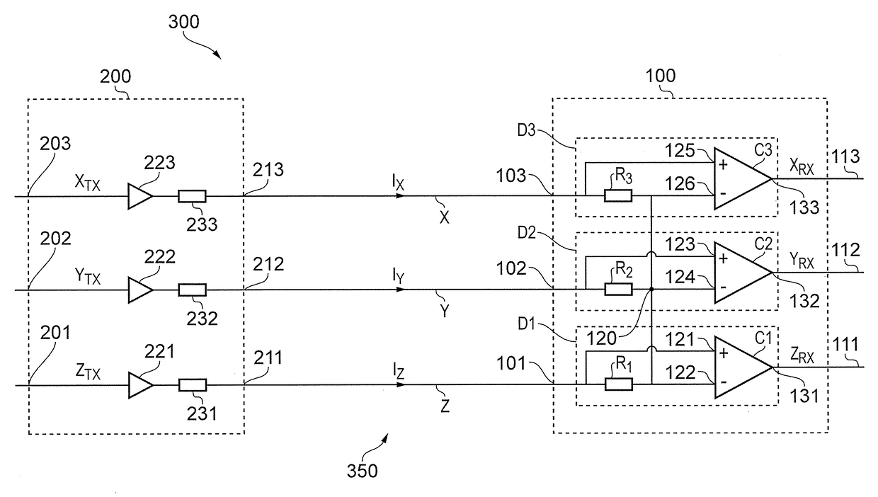
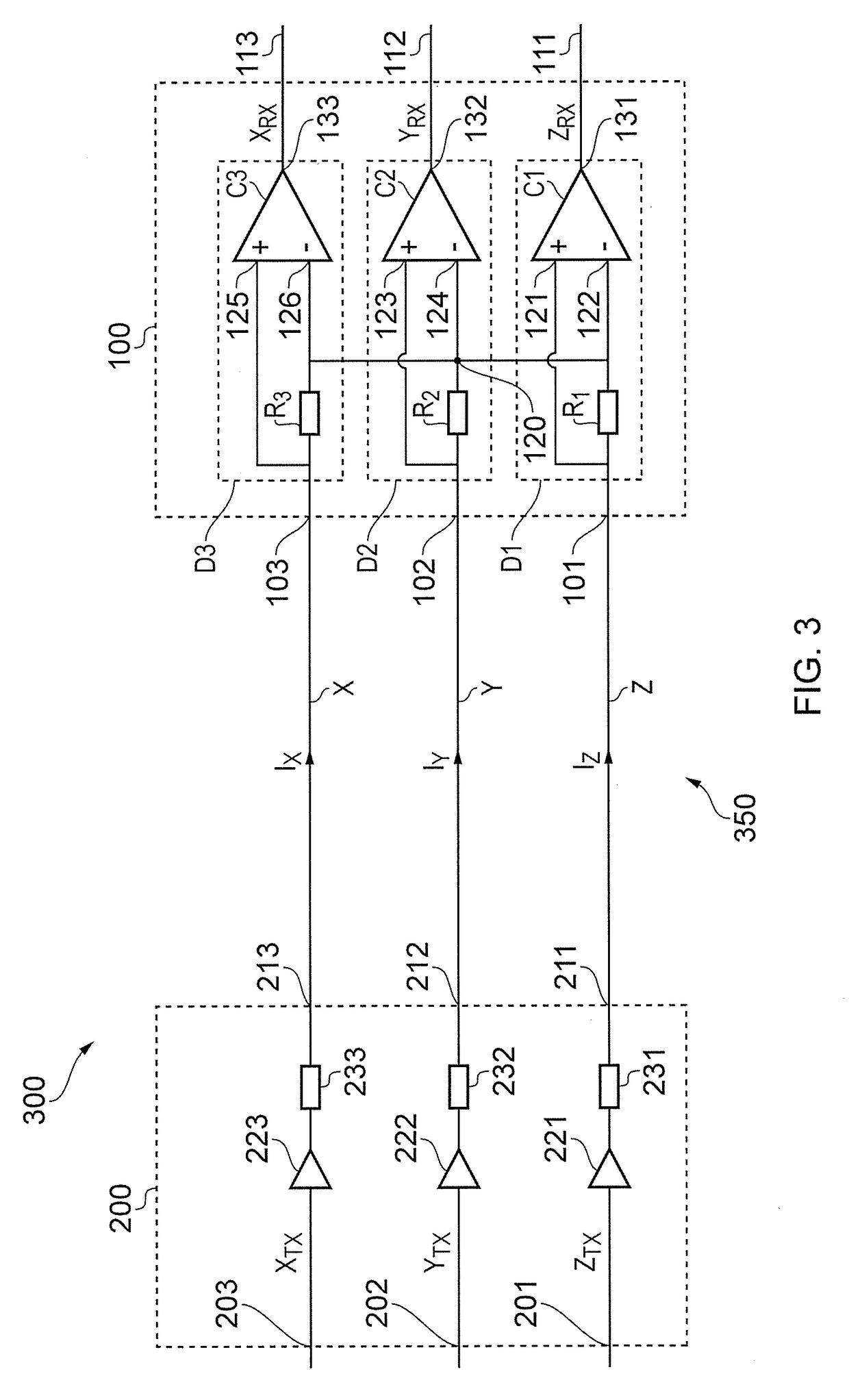
[0006]According to a first aspect there is provided a receiver for an N-wire digital interface, where N is any integer exceeding two, the receiver comprising:

[0007]N input terminals, a common node and N detection stages;

[0008]wherein each of the N detection stages comprises[0009]a resistive element coupled between the common node and a respective one of the N input terminals, and[0010]a comparator having a first input coupled to the respective one of the N input terminals and a second input coupled to the common node; and

[0011]wherein the resistive element of each of the detection stages has substantially the same resistance.

[0012]The receiver enables an N-wire digital interface to employ two-level signals which can provide low timing skew and low signal distortion using a simple transmitter with single ended drivers. Such a two-level driver can enable good impedance matching at the transmitter so that the receiver does not need to be matched. The resistive elements at the receiver ...


PUM


Abstract

A receiver for an N-wire digital interface, where N is any integer exceeding two, has N input terminals, a common node and N detection stages. Each of the N detection stages has a resistive element coupled between the common node and a respective one of the N input terminals, and a comparator having a first input coupled to the respective one of the N input terminals and a second input coupled to the common node.

Description

FIELD OF THE DISCLOSURE[0001]The present disclosure relates to a receiver for an N-wire digital interface, a signalling system comprising the receiver, a wireless communication device comprising the signalling system, and a method of operating a signalling system.BACKGROUND TO THE DISCLOSURE[0002]The digital interface between radio frequency integrated circuits (RFICs) and baseband integrated circuits (BBIC) has to support increasingly high data rates with wireless communication standards such as the Third Generation Partnership Project (3GPP) Long Term Evolution (LTE) standard employing carrier aggregation. Digital interface standards are specified by the Mobile Industry Processor Interface (MIPI) Alliance. The current MIPI DigRF v4 draft interface requires a 5.2 GHz clock for transmitting data in the LTE 20+20+20 case, denoting aggregation of three 20 MHz portions of spectrum, rendering the physical implementation very challenging. These extremely high clock rates are required bec...

Claims


Application Information

Patent Timeline
Patent Type & Authority Patents(United States)
IPC IPC(8): H04L27/00H04B7/06H04L25/02H04L25/49
CPCH04L25/4917H04B7/06H04L25/0272H04L25/0292
Inventor KOLI, KIMMO
Owner TELEFON AB LM ERICSSON (PUBL)
Why Eureka
Try Eureka