
Control device for an internal combustion engine
a control device and internal combustion engine technology, applied in the direction of electric control, machines/engines, mechanical equipment, etc., can solve the problems of inability to greatly increase the amount of intake air, low thermal efficiency in an operating region in which the load of the internal combustion engine is relatively low, and inability to achieve the great effect of improving thermal efficiency
- Summary
- Abstract
- Description
- Claims
- Application Information
AI Technical Summary
Benefits of technology
Problems solved by technology
Method used
Image

Examples
first embodiment
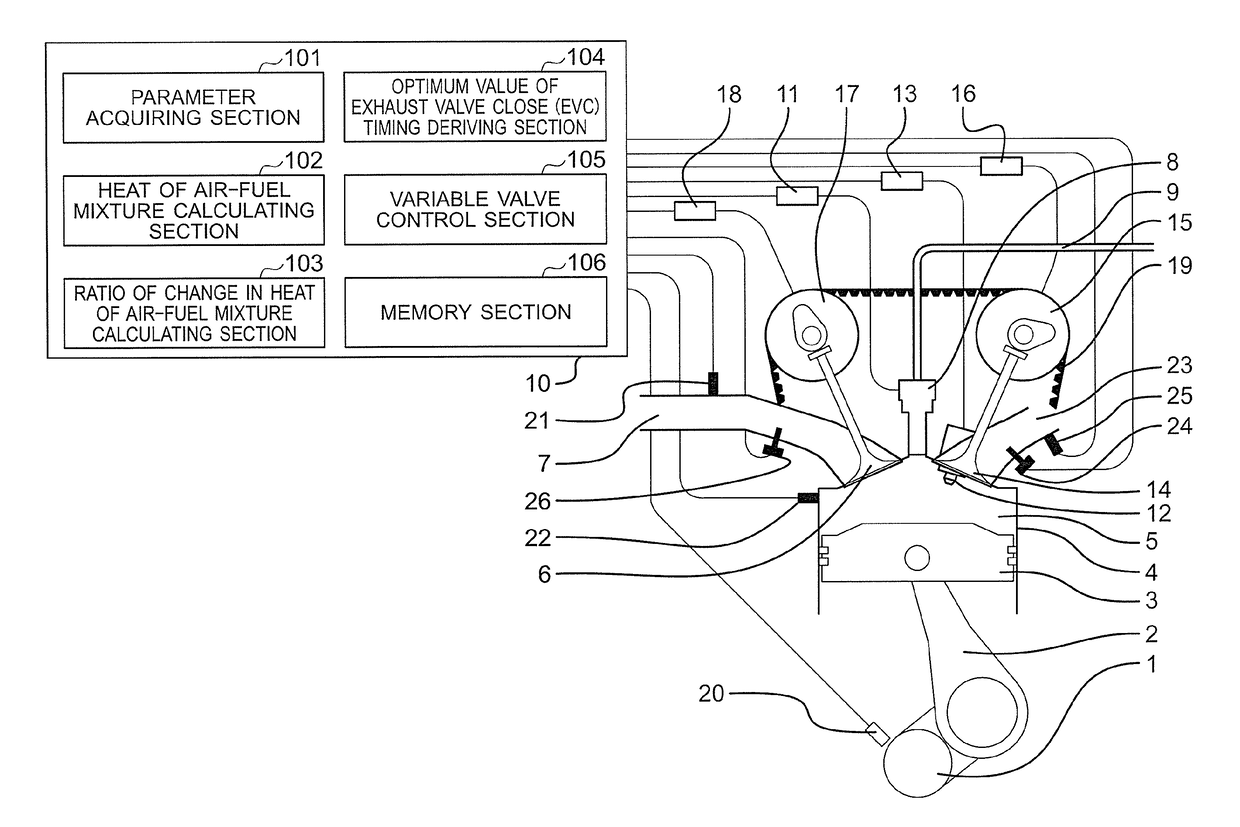
[0025]First, in order to clarify technical features of the present invention, a problem of an internal combustion engine with the application of the related art described in Japanese Patent Application Laid-open No. 2009-150288, which the inventors of the present invention newly focus on, is described referring to FIG. 4. FIG. 4 is an explanatory diagram showing an example of a database for setting a valve-closing timing of an exhaust valve with the application of the related art.
[0026]In this case, an internal EGR gas is a part of a combustion gas derived in a previous cycle, which is left in a combustion chamber. Further, as a result of mixture of the internal EGR gas and air and a fuel that are newly taken and supplied in a current cycle, an air-fuel mixture is formed. Combustion of the thus formed air-fuel mixture is significantly affected by a temperature and a density of the air-fuel mixture.
[0027]The internal EGR gas temperature is high relative to an air temperature and a co...
second embodiment
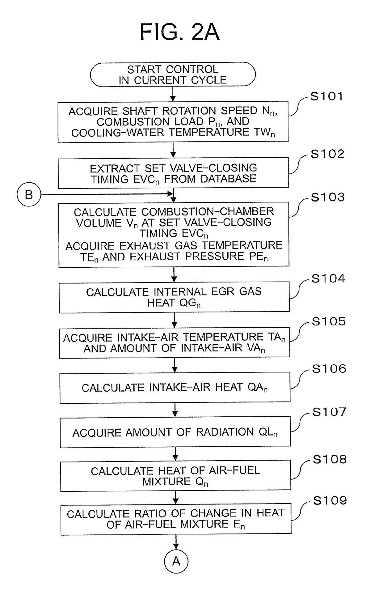
[0099]In the first embodiment described above, the case where the optimum value of exhaust valve close (EVC) timing for allowing the absolute value of the ratio of change in heat of air-fuel mixture to become equal to or smaller than the reference value is derived is described. On the other hand, in a second embodiment of the present invention, the following configuration is described. Specifically, the heat of air-fuel mixture in the previous cycle is adjusted so as to be increased or decreased in the current cycle in accordance with a magnitude relationship between the combustion load in the previous cycle and that in the current cycle. In addition, the optimum value of exhaust valve close (EVC) timing for allowing the absolute value of the ratio of change in heat of air-fuel mixture to become equal to or smaller than the reference value is derived.
[0100]Here, as compared with a case of a steady combustion with a small combustion load, the temperature of the internal EGR gas remai...
PUM
 Abstract
Description
Claims
Application Information