Method and apparatus for reducing phosphorus in crude refining

a technology of crude refining and phosphorus, which is applied in the field of crude refining methods and equipment for reducing phosphorus in crude refining, can solve the problems of unsatisfactory and inefficient heating of crude oil past 350-400° f., strain on the entire refining system components, and low phosphorus levels downstream in the crude heater and other vessels, so as to increase the temperature of crude oil and reduce the temperature of the product , the effect of increasing the efficiency o

Active Publication Date: 2017-05-23
MARATHON PETROLEUM
View PDF2 Cites 1 Cited by
  • Summary
  • Abstract
  • Description
  • Claims
  • Application Information

AI Technical Summary

Benefits of technology

[0004]The present invention provides an apparatus and method for the reduction of fouling in the refining of crude oil due to Phosphorous.
[0006]The removal of the additional contaminants and light hydrocarbons, specifically kerosene at the flash tower or flash drum, results in lower phosphorus levels downstream in the crude heater and other vessels. This reduction in phosphorus has been shown to decrease unwanted fouling in downstream vessels. This discovery runs contrary to the long held belief that heating the crude oil past 350-400° F. was undesirable and inefficient. If the crude oil is to be maintained in a liquid state prior to flashing, the pressure of the crude oil must be increased to maintain the crude oil in a liquid state when the temperature is increased to 450-500° F. Pursuant to the ideal gas law, PV=nRT, an increased temperature requires an increased pressure to maintain the liquid phase. This increased pressure results in a strain on the entire refining system components, resulting in a shorter replacement cycle for the components. Therefore, it was believed to be undesirable and inefficient to maintain the crude oil in a liquid state and operate at a higher temperature. We have discovered, however the benefits of raising the crude oil to 450-500° F., prior to flashing; the phosphorus in the crude oil is reduced significantly, and the phosphorous remaining is not in a form that induces fouling, thus downstream fouling is greatly reduced. We have discovered that the benefits of raising the temperature of the crude oil outweighs the risk of straining the refinery system components.
[0007]In the preferred embodiment, multiple heat exchangers are used to raise the crude oil to a range of 450-500° F. prior to flashing. Once the crude oil enters the flash drum, or flash tower, the higher temperature results in more light hydrocarbon chains, including kerosene, and water being removed from the crude oil prior to entering the crude heater. The light hydrocarbons flash from the crude oil and are passed to a fractionation tower and on to the crude tower, bypassing the remaining preheat circuit and crude heater. This reduction in light hydrocarbons reduces the phosphorus found in the crude oil, thereby reducing fouling in the crude heater and downstream vessels.
[0008]Another element of the present invention provides that the flashed light hydrocarbons, specifically the tower bottoms, are routed directly to the crude tower and bypass other vessels downstream that have normally experienced significant fouling. These tower bottoms bypass the preflash exchanger train (a number of heat exchangers) and the crude heater. By directing the tower bottoms around the preflash exchanger train and the crude heater, phosphorous levels are decreased in the preflash exchanger train and the crude heater and results in significantly less fouling of the components.

Problems solved by technology

The removal of the additional contaminants and light hydrocarbons, specifically kerosene at the flash tower or flash drum, results in lower phosphorus levels downstream in the crude heater and other vessels.
This discovery runs contrary to the long held belief that heating the crude oil past 350-400° F. was undesirable and inefficient.
This increased pressure results in a strain on the entire refining system components, resulting in a shorter replacement cycle for the components.
Therefore, it was believed to be undesirable and inefficient to maintain the crude oil in a liquid state and operate at a higher temperature.

Method used


Image

  • Method and apparatus for reducing phosphorus in crude refining
  • Method and apparatus for reducing phosphorus in crude refining

Examples


Embodiment Construction

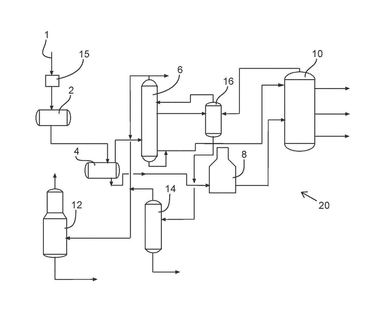
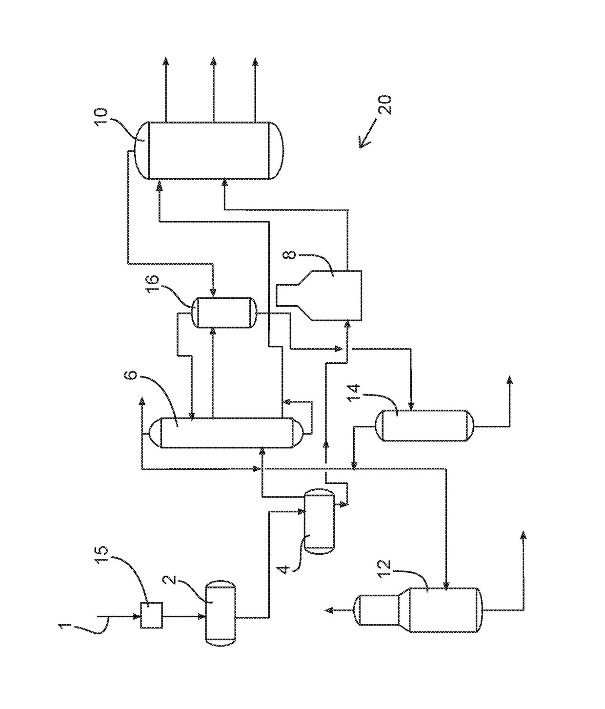
[0011]Referring now to the FIGURE, the crude oil 1, or raw crude, enters the refinery from a pipeline at ground temperature of about 50-70° F. The crude oil 1 is stored in tanks (not shown) until it is transferred to the crude unit 20, where it is heated by passage through at least one heat exchangers 15 to increase the temperature of the crude oil 1 to approximately 300° prior to entering a desalter 2. The heat exchangers increase the temperature of the crude oil 1 while, reducing the temperature of the finished product. Crude oil enters a desalter 2 where salt is removed, or washed, from the crude. The crude oil, now called desalted crude, is pumped through additional heat exchangers, raising the temperature in excess of 450° F., before entering a flash drum 4. In the preferred embodiment, the desalted crude is heat to 500° F. In the flash drum 4 light hydrocarbons and contaminants contained in the crude oil are vaporized, or flashed, and are thus removed from the desalted crude. ...


PUM

PropertyMeasurementUnit
temperatureaaaaaaaaaa

Abstract

A method and apparatus for the reduction of fouling in a crude unit. Chemicals containing Phosphorous are understood to be utilized in the production or transportation of certain types of crude oils. It is believed that the elevated levels of phosphorus are contributing to the excessive fouling observed in the preheat exchanger circuits and crude heaters.

Description

CROSS REFERENCE TO RELATED APPLICATION[0001]The present patent application claims the benefit of U.S. provisional patent application No. 62 / 050,993 filed Sep. 16, 2014.BACKGROUND OF THE INVENTION[0002]At an oil refinery, crude oil is brought in, generally through a pipeline, at a temperature of approximately 50-70° F. Before the crude oil enters a crude heater, the crude is pre-heated to a desired temperature to optimize the performance of the crude heater and reduce fuel costs. Once the crude oil is pre-heated to a desired temperature of 350-400° F., it enters a flash drum or flash tower, wherein the lighter hydrocarbons (such as butane, propane and gasoline) are removed from the crude oil by evaporation or flashing. The remaining crude oil is then transferred to the crude heater for further heating prior to separation in the crude tower.[0003]It is well known that fouling in the preheat circuit, progressively worsens as the crude temperature increases, cumulating with the most ext...

Claims


Application Information

Patent Timeline
Patent Type & Authority Patents(United States)
IPC IPC(8): C10G31/06C10G7/00C10G75/00C10G31/00
CPCC10G75/00C10G7/00C10G31/06C10G2300/202C10G2400/08
Inventor JOHNSON, JAMES F.ADAMS, PHILLIP RYAN
Owner MARATHON PETROLEUM
Why Eureka
Try Eureka