Method for attitude controlling based on finite time friction estimation for flexible spacecraft

a flexible spacecraft and finite time friction technology, applied in the field of astronautic technologies, can solve the problems of affecting the accuracy of spacecraft attitude control, increasing the appendage and increasing the size of the spacecraft body, and achieves high-precision attitude control and quick track the friction force of the flywheel

Active Publication Date: 2017-05-30
BEIHANG UNIV
View PDF2 Cites 33 Cited by
  • Summary
  • Abstract
  • Description
  • Claims
  • Application Information

AI Technical Summary

Benefits of technology

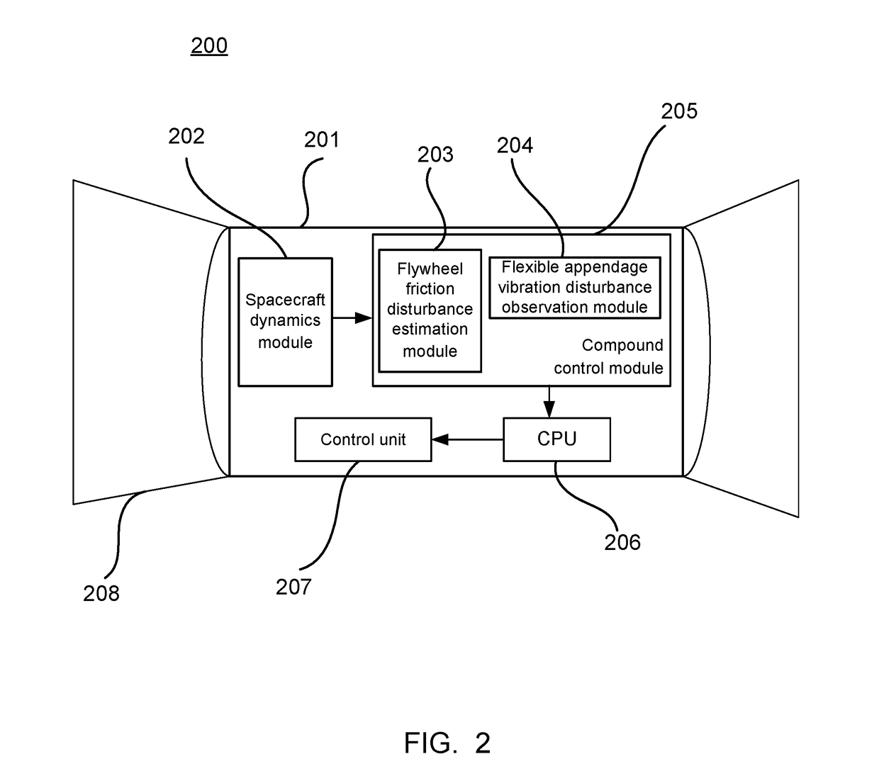
[0053]The method for attitude controlling based on finite time friction estimation for a flexible spacecraft according to the present invention can quickly track the friction force of the flywheel system, control the friction disturbance of the flexible spacecraft and the vibration disturbance of the flexible appendage, and realize high precision attitude control for the flexible spacecraft system.

Problems solved by technology

These requirements result in increasingly larger appendages of the spacecraft.
However, if a large number of flexible appendages are used, attitude control of the spacecraft body will be affected.
Because the flexible structures will incur vibration during motion of the spacecraft body, which will affect the accuracy of spacecraft attitude control.
However, the flywheel has a very distinctive feature, that is, limited by processing conditions, a friction moment is generated when the speed of the flywheel is low and crosses zero, affecting the spacecraft attitude control system.
Even in some cases, because the rotational speed of the flywheel repeatedly crosses zero, the flywheel chatters, and causes chattering of the spacecraft body with flexible appendages and further causes chattering of the flexible appendages, making it more difficult to stabilize the spacecraft system and implement high-precision attitude control.

Method used


Image

  • Method for attitude controlling based on finite time friction estimation for flexible spacecraft
  • Method for attitude controlling based on finite time friction estimation for flexible spacecraft
  • Method for attitude controlling based on finite time friction estimation for flexible spacecraft

Examples


Embodiment Construction

[0059]Objects and functions of the present invention as well as methods for realizing these objects and functions will be elucidated with reference to exemplary embodiments. However, the present invention is not limited to the following disclosed exemplary embodiments, but may be implemented in different ways. The description of the invention is merely provided to assist those of ordinary skill in the art in a comprehensive understanding of specific details of the invention in nature.

[0060]As used herein, the term “module” may refer to, be part of, or include an Application Specific Integrated Circuit (ASIC); an electronic circuit; a combinational logic circuit; a field programmable gate array (FPGA); a processor (shared, dedicated, or group) that executes code; other suitable hardware components that provide the described functionality; or a combination of some or all of the above, such as in a system-on-chip. The term module may include memory (shared, dedicated, or group) that st...


PUM


Abstract

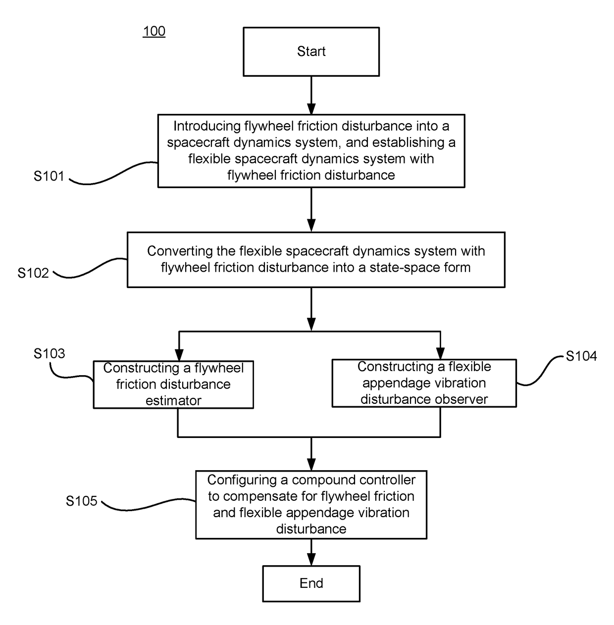
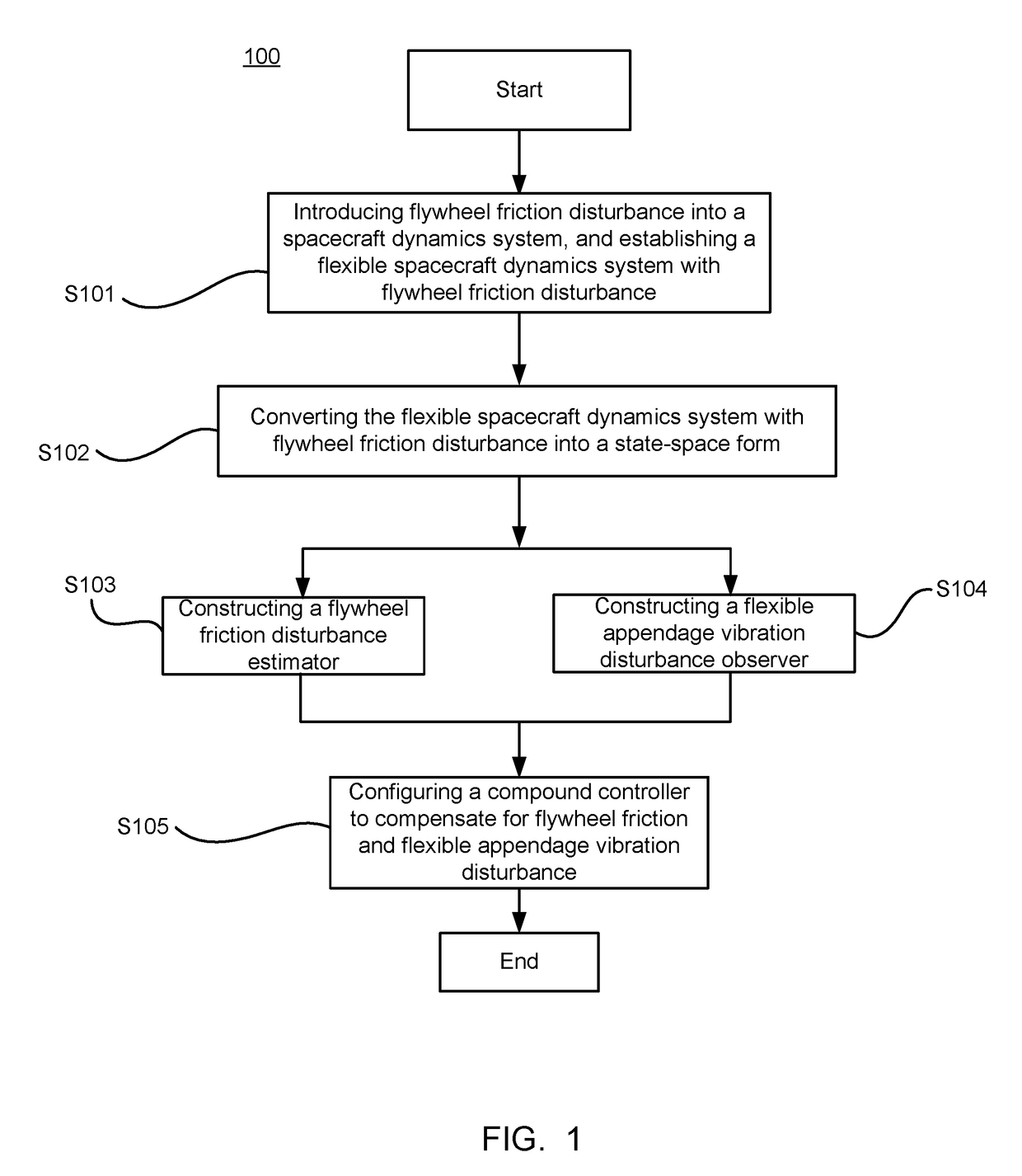
The present invention provides a method for attitude control based on finite time friction estimation for a flexible spacecraft. The control method includes the following steps: a. introducing spacecraft flywheel friction disturbance into a spacecraft dynamics system, and establishing a flexible spacecraft dynamics system with flywheel friction disturbance; b. converting the flexible spacecraft dynamics system with flywheel friction disturbance into a state-space form; c. constructing a flywheel friction disturbance estimator; d. constructing a flexible appendage vibration disturbance observer; and e. combining the flywheel friction disturbance estimator in the step c and the flexible appendage vibration disturbance observer in the step d with a nominal controller to obtain a compound controller; the compound controller compensating for flywheel friction according to an estimated value of a flywheel friction moment; and the compound controller compensating for flexible appendage vibration disturbance according to an estimated value of flexible appendage vibration disturbance.

Description

CROSS-REFERENCE TO RELATED APPLICATIONS[0001]This non-provisional application claims priority to and benefit of, under 35 U.S.C. §119(a), Patent Application No. 201610357659.1 filed in P.R. China on May 26, 2016, the entire content of which is hereby incorporated by reference.FIELD OF THE INVENTION[0002]The present invention relates to the field of astronautic technologies, and more particularly to a method for attitude controlling based on finite time friction estimation for a flexible spacecraft.BACKGROUND OF THE INVENTION[0003]Spacecraft attitude control system is an important element among various systems of a spacecraft. The precision, stability, and reliability of spacecraft attitude control are key technologies during the research process of spacecrafts. In recent years, spacecrafts need to be responsible for more complex tasks and therefore have a continuously increasing demand for electric power. Accordingly, a larger solar panel is needed in order to meet the demand of the...

Claims


Application Information

Patent Timeline
Patent Type & Authority Patents(United States)
IPC IPC(8): B64G1/36B64G1/28B64G1/24F16F15/30
CPCB64G1/283B64G2001/245F16F15/30B64G1/244B64G1/245
Inventor GUO, LEIZHANG, PEIXIQIAO, JIANZHONGZHU, YUKAIXU, JIANWEI
Owner BEIHANG UNIV
Why Eureka
Try Eureka