Illumination system of a microlithographic projection exposure apparatus

a technology of exposure apparatus and exposure system, which is applied in the direction of microlithography exposure apparatus, photomechanical treatment, instruments, etc., can solve the problems of reducing the sensitivity of the optical integrator to transient variations of the angular light distribution of the incoming light, and achieves significant or even complete reduction of the main adverse effect of optical crosstalk, reducing the sensitivity, and increasing the divergence

Active Publication Date: 2017-06-06
CARL ZEISS SMT GMBH
View PDF17 Cites 1 Cited by
  • Summary
  • Abstract
  • Description
  • Claims
  • Application Information

AI Technical Summary

Benefits of technology

[0020]The inventor has perceived that optical crosstalk cannot be completely avoided even if the optical integrator increases the divergence only slightly and the input divergence is small. However, it is possible to eliminate the main adverse effect of optical crosstalk caused by diffracted light, namely the sensitivity of the optical integrator to transient variations of the angular light distribution of the incoming light. It has been found that if the first lenses are not arranged in the front focal plane of the second lenses, but a bit further away from it, this sensitivity can be significantly or even completely reduced. Since the second focal length f2 typically is in the range of several hundred millimeters in the case of optical integrators that increase the divergence only slightly, an increase of the distance by only 1% implies that the distance between the optical raster plates will be increased by at least some millimeters, and often by some centimeters.
[0021]The increase of the distance between the first and second optical raster plate has the effect that changes of the far field spatial irradiance distribution, which are produced by diffracted light contributing to optical crosstalk if the angular light distribution on the first optical raster plate varies, are compensated for. This exploits the inverting effect of the second lenses. However, only a rigorous computation that takes into account the wave nature of the light can fully explain how the defocused arrangement of the first lenses reduces the sensitivity of the optical integrator to transient variations of the angular light distribution of the incoming light.
[0024]In some embodiments the number k is below 40, in others below 20 and in still further embodiments below 10. The smaller the number k is, the greater will be the benefits that are obtained by increasing the distance d between the optical raster plates beyond the conventional value of the focal length f2 of the second lenses.

Problems solved by technology

However, only a rigorous computation that takes into account the wave nature of the light can fully explain how the defocused arrangement of the first lenses reduces the sensitivity of the optical integrator to transient variations of the angular light distribution of the incoming light.

Method used


Image

  • Illumination system of a microlithographic projection exposure apparatus
  • Illumination system of a microlithographic projection exposure apparatus
  • Illumination system of a microlithographic projection exposure apparatus

Examples


Embodiment Construction

I. General Construction of Projection Exposure Apparatus

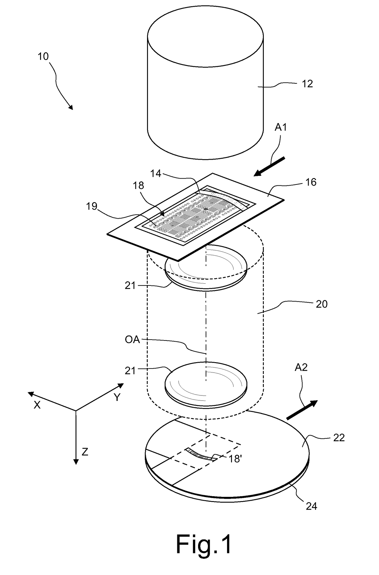
[0056]FIG. 1 is a perspective and highly simplified view of a projection exposure apparatus 10 in accordance with the present invention. The apparatus 10 comprises an illumination system 12 which produces a projection light beam. The latter illuminates a field 14 on a mask 16 containing a pattern 18 of fine features 19. In this embodiment the illuminated field 14 has the shape of a ring segment. However, other shapes of the illuminated field 14, for example rectangles, are contemplated as well.

[0057]A projection objective 20 having an optical axis OA and containing a plurality of lenses 21 images the pattern 18 within the illuminated field 14 onto a light sensitive layer 22, for example a photoresist, which is supported by a substrate 24. The substrate 24, which may be formed by a silicon wafer, is arranged on a wafer stage (not shown) such that a top surface of the light sensitive layer 22 is precisely located in an image plan...


PUM

PropertyMeasurementUnit
focal length f2aaaaaaaaaa
wavelengthaaaaaaaaaa
wavelengthsaaaaaaaaaa

Abstract

An illumination system of a microlithographic projection exposure apparatus comprises an optical integrator, which includes a first optical raster plate and a second optical raster plate. The first second optical raster plate comprising an array of first lenses having, along a reference direction, a first focal length f1, and the second optical raster plate comprises an array of second lenses having, along the reference direction, a second focal length f2. The vertices of the first lenses and vertices of the second lenses are spaced apart by a distance d that is greater than the second focal length f2 so that d>1.01·f2. This ensures that laser pointing or another transient variation of the illumination of the optical integrator does not adversely affect the spatial irradiance distribution in a plane which is illuminated by the optical integrator.

Description

CROSS-REFERENCE TO RELATED APPLICATIONS[0001]The present application is a continuation of, and claims benefit under 35 USC 120 to, international application PCT / EP2012 / 004511, filed Oct. 27, 2012, the entire disclosure of which is incorporated by reference herein.BACKGROUND OF THE INVENTION[0002]1. Field of the Invention[0003]The invention generally relates to an illumination system of a microlithographic projection exposure apparatus, and in particular to an apparatus comprising an array of micromirrors or other beam deflecting elements that can be individually controlled.[0004]2. Description of Related Art[0005]Microlithography (also referred to as photolithography or simply lithography) is a technology for the fabrication of integrated circuits, liquid crystal displays and other microstructured devices. The process of microlithography, in conjunction with the process of etching, is used to pattern features in thin film stacks that have been formed on a substrate, for example a si...

Claims


Application Information

Patent Timeline
Patent Type & Authority Patents(United States)
IPC IPC(8): G03F7/20G02B27/09G02B3/00G02B26/08
CPCG03F7/70075G02B3/0062G02B26/0816G02B27/0905G02B27/0961G03F7/7015G03F7/70066
Inventor PATRA, MICHAEL
Owner CARL ZEISS SMT GMBH
Why Eureka
Try Eureka