
Probe card

a technology of probe cards and probes, applied in the field of probe cards, can solve the problems of large difference between probe marks at room temperature and high temperature, serious above situations, serious affecting the electrical detection function of the probe cards, etc., to reduce the deviation problem, reduce the number and frequency of production abnormalities, and reduce the offset of the needle tip

Active Publication Date: 2017-06-13
GLOBAL UNICHIP CORPORATION +1
View PDF6 Cites 0 Cited by
  • Summary
  • Abstract
  • Description
  • Claims
  • Application Information

AI Technical Summary

Benefits of technology

The solution effectively reduces needle tip offset deviations, ensuring accurate probe mark locations across temperature variations, reducing production abnormalities and debugging time, and facilitates effortless setup for multi-DUT testing without compromising probe alignment.

Problems solved by technology

However, the thermal stream of the thermal radiation is actually dynamic, so the probes may face different thermal energy impacts, which results in that the three-dimensional positions of the needle tips cannot be determined and further causes a large difference between probe marks respectively at room temperature and a high temperature.
The above situations become serious especially to the probe cards having large probing areas, such as multi-DUT probe cards.
When the location of the probe mark is not precise, some probes may not precisely contact the pads or bumps on the DUT when testing, which will seriously affect the electrical detection functions of the probe card.
Because the foregoing deviation problem of offset of the probe marks occurs frequently, it tends to increase the length of debugging time and setting multi-DUT probe markings.

Method used


Image

  • Probe card
  • Probe card
  • Probe card

Examples


Embodiment Construction

[0024]Reference will now be made in detail to the present embodiments of the disclosure, examples of which are illustrated in the accompanying drawings. Wherever possible, the same reference numbers are used in the drawings and the description to refer to the same or like parts.

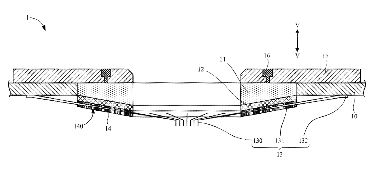
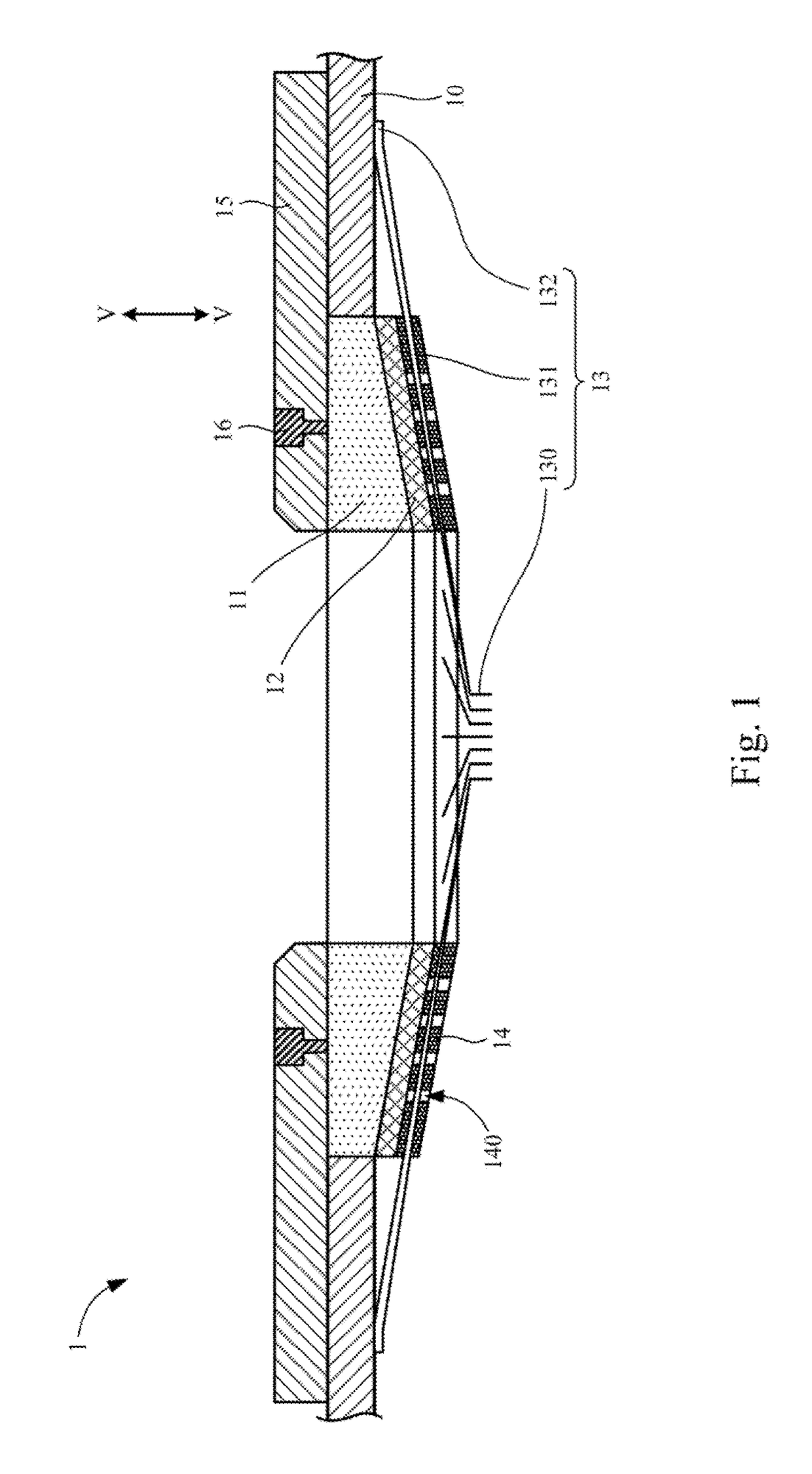
[0025]FIG. 1 is a side cross-sectional view of a probe card 1 according to an embodiment of the disclosure. The probe card 1 shown in FIG. 1 is a probe card for testing CISs (CMOS Image Sensors) as an example, which has an aperture at the center for light to pass through. However, the disclosure is not limited in this regard, and various kinds of probe cards can utilize the core concepts of the disclosure.

[0026]As shown in FIG. 1, in the embodiment, the probe card 1 includes a circuit board 10, an insulating base 11, a plurality of probes 13, and at least one deviation-compensating member 12. An end of each of the probes 13 is connected to the circuit board 10. In more detail, each of the probes 13 has a need...


PUM


Abstract

A probe card includes a circuit board, a plurality of probes, and at least one deviation-compensating member. An end of each of the probes is connected to the circuit board. The deviation-compensating member is fixed to the circuit board and connected to the probes. The probes have a first thermal expansion characteristic, the deviation-compensating member has a second thermal expansion characteristic, and the first thermal expansion characteristic and the second thermal expansion characteristic are different.

Description

RELATED APPLICATIONS[0001]This application claims priority to China Application Serial Number 201510388747.3, filed Jul. 6, 2015, which is herein incorporated by reference.BACKGROUND[0002]Technical Field[0003]The present disclosure relates to a probe card.[0004]Description of Related Art[0005]The main purpose of a probe card is to achieve automated measurement by directly contacting the probes to the pads or bumps on the DUTs (Device Under Test, such as a chip) and coordinating with peripheral testing machines and software controlling. Therefore, the electrical characteristics and performances of the DUTs can be ensured to comply with the design specifications, and defective products can be effectively screened. The actual testing procedures generally are transmitting testing signals from the testing machines to the DUTs through the probe card, and returning the testing results from the DUTs to the testing machines through the probe card to be further analyzed.[0006]The probe card h...

Claims


Application Information

Patent Timeline
Patent Type & Authority Patents(United States)
IPC IPC(8): G01R1/44G01R1/073
CPCG01R1/07314G01R1/44G01R35/005G01R31/2863G01R31/2875
Inventor LIAO, CHIH-CHIEHSUN, YU-MINCHENG, CHIH-FENG
Owner GLOBAL UNICHIP CORPORATION
Learn More