Temperature-dependent switch

a technology of temperature-dependent switch and switch body, which is applied in the direction of electric switch, electrical apparatus, contact, etc., can solve the problems of insufficient mechanical stability, deformation of bimetallic snap-action disc, and inability to always be desirable, and achieves good thermal coupling of heating resistor, simple and inexpensive design, and good mechanical hold

Active Publication Date: 2017-06-27
THERMIK GERATEBAU
View PDF42 Cites 6 Cited by
  • Summary
  • Abstract
  • Description
  • Claims
  • Application Information

AI Technical Summary

Benefits of technology

[0036]In view of this prior art, it is one object of the present invention to develop the switch mentioned at the outset such that, given a simple and inexpensive design, good thermal coupling of the heating resistor to the switch and at the same time a good mechanical hold between the switch and the heating resistor is realized.
[0039]By virtue of the welding, the thermal connection of the heating resistor to the housing is realized in a manner which is simple in design terms and inexpensive. If the housing is electrically conductive where the heating resistor is welded, the electrical connection to one of the two first connections is also produced at the same time by the welding when the conductive housing either already acts as one of the first connections or, in accordance with the invention, is connected to one of the first connections. The other first connection of the switch and a further connection provided on the heating resistor are then used for the external connection of the switch, for example by soldering on connection strands.
[0046]It is advantageous here that, owing to the welding operation, both the thermal and the electrical connection to the switch is performed, which contributes to low manufacturing costs. The invention can therefore be used for all switches which have at least one current-conducting housing part or an electrically conductive housing or housing part, to which one of the first connections is or can be connected.
[0049]By virtue of spot-welding spots, the metal part can be fastened to the housing in a simple and inexpensive manner, wherein the electrical and thermal connections are defined by the welding spots, which is advantageous in particular when setting the resistance value of the metal part. The operating current and the Joule heat are therefore conducted into the housing through the point-like welding spots.
[0051]The further connection can therefore either be within the contour of the housing or laterally next to the bottom or cover or above or below the housing. Depending on the respective application cases, starting from the metal part welded to the housing on the outside in accordance with the invention, the position of one of the external connections can therefore be selected as desired in a manner which is simple in design terms and inexpensive.
[0057]While it is quite sufficient if only a bimetallic snap-action disc is provided, which both conducts the operating current and produces the contact pressure and ensures temperature-dependent opening, by virtue of a spring snap-action disc, which, in addition to the bimetallic snap-action disc or on its own, effects the contact pressure, the bimetallic snap-action disc can be relieved of mechanical and electrical load in its low-temperature position, which contributes to greater long-term stability of its switching response.

Problems solved by technology

It is not only problematic to produce this connection, additionally it also has insufficient mechanical stability, for which reason the document discloses that heat-shrink tubing is shrunk onto the switch and the mounting plate together, and the two connection strands protrude out of said heat-shrink tubing laterally.
If the temperature increases beyond a permissible value, either as a result of an excessively high operating current or as a result of an excessively heated appliance to be protected, the bimetallic snap-action disc deforms, as a result of which the switch is opened and the supply to the appliance to be protected is interrupted.
While such a switching response may be quite sensible for protecting a hairdryer, for example, this is not always desirable when the appliance to be protected should not automatically switch on again after shutdown in order to avoid damage.
In particular when the known switches are used for protecting high-power motors, they need to be able to be subjected to a very high mechanical load owing to the severe vibrations occurring during operation and in particular during run-up of the motors.
This high current naturally also results in heating of the motor and therefore in a temperature increase at the switch.
However, this heating-up takes place so slowly that the motor may already be irreversibly destroyed before the switch responds as a result of the increase in the motor temperature.
Even in the case of suitable matching between the response temperature of the bimetallic snap-action disc and the resistance value of the heating resistor on its own, these two contradictory conditions cannot be met in the above-described known switches, however.
The switching response set in this way is only achieved during the steady-state operation, however, i.e. if sufficient time has lapsed in order for the switch to open, either when the temperature of the motor is too high or else when the current is too high.
In the case of relatively high operating currents of 10 amperes or more, the number of switching cycles is markedly reduced, however, because the temperature change at the soldered joints between the lower part and the mounting plate result in the soldered joints being damaged as a result of fatigue failure after approximately 1000 switching cycles to such a great extent that the current flow is interrupted and the switch is not operational.
With this known switch, the design described to this extent entails the risk that, when handled improperly, a force is exerted on the mounting plate and / or the housing, which force results in the soldered joints breaking or at least being weakened.

Method used


Image

  • Temperature-dependent switch
  • Temperature-dependent switch
  • Temperature-dependent switch

Examples


Embodiment Construction

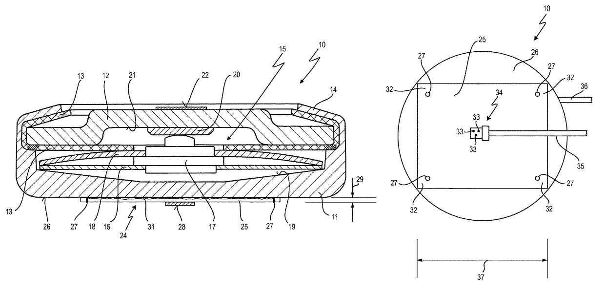
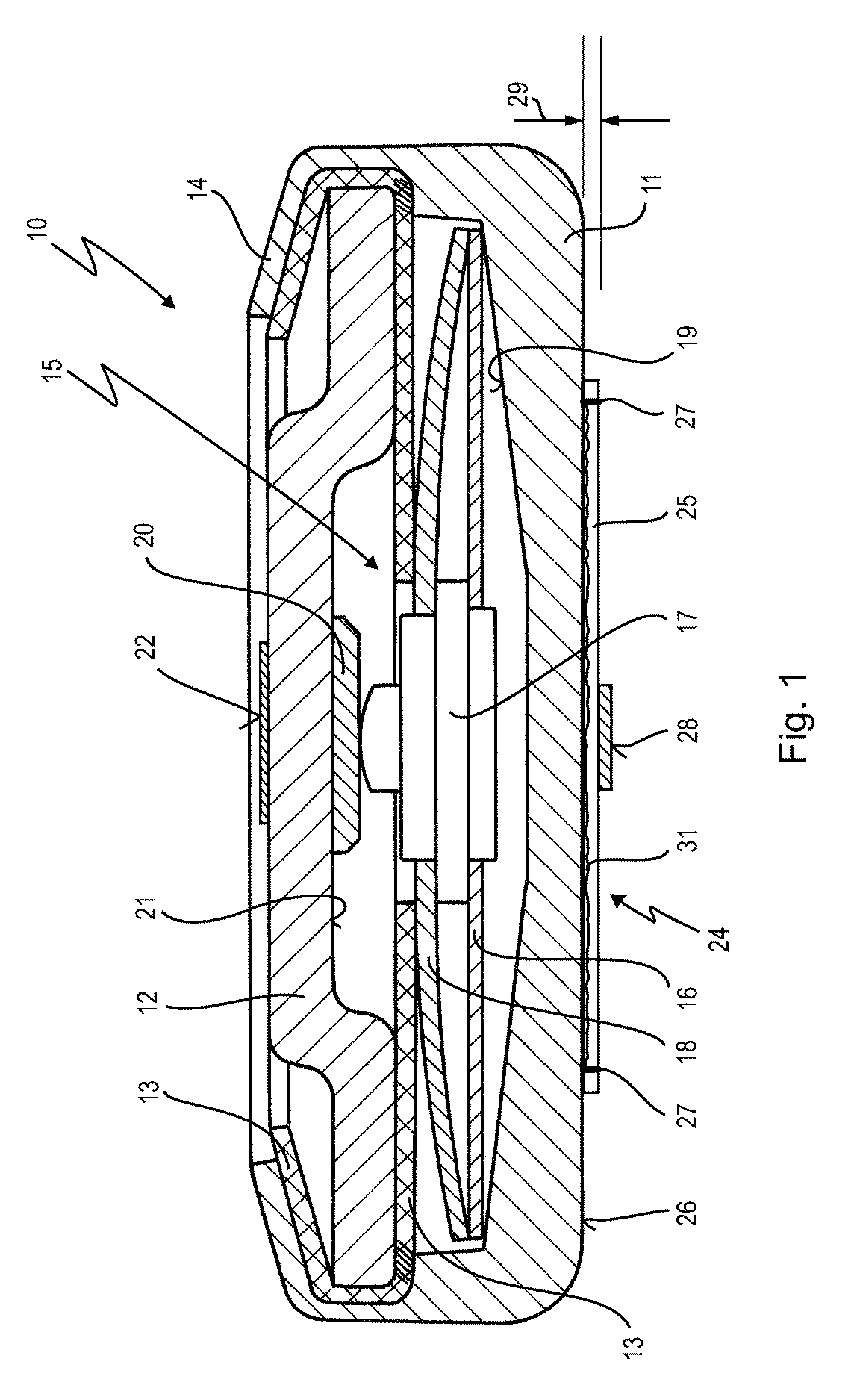
[0076]In FIG. 1, 10 denotes a temperature-dependent switch which comprises a pot-like lower part 11, which is closed by an upper part 12, which is held on the lower part 11—with an insulation film 13 interposed—by a flanged rim 14.

[0077]A temperature-dependent switching mechanism 15 which comprises a spring snap-action disc 16, which centrally supports a movable contact part 17 on which a freely inserted bimetallic disc 18 rests, is arranged in the housing of the switch 10, which housing is formed by the lower part 11 and the upper part 12.

[0078]The spring snap-action disc 16 is supported on an inner bottom 19 on the inside on the lower part 11, which is manufactured from electrically conductive material.

[0079]The movable contact part 17 is in bearing contact with a stationary contact part 20, which is provided on an inner side 21 of the upper part 12, which in this embodiment is likewise manufactured from metal, although it is sufficient for the embodiment of the invention if the h...


PUM


Abstract

A temperature-dependent switch has a temperature-dependent switching mechanism, a housing accommodating the switching mechanism, two first connections between which first connections the switching mechanism makes or interrupts an electrically conductive connection depending on the temperature of said switching mechanism, and a heating resistor that is arranged on an outside of the housing and is connected electrically in series with the two connections. The heating resistor is a sheet-like metal part that is welded to the housing and carries a further connection.

Description

RELATED APPLICATION[0001]This application claims priority to German patent application DE 10 2013 108 508, filed Aug. 7, 2013, which is incorporated herein by reference.BACKGROUND OF THE INVENTION[0002]Field of the Invention[0003]The present invention relates to a temperature-dependent switch comprising a temperature-dependent switching mechanism, a housing accommodating the switching mechanism, two first connections provided on the switch, between which first connections the switching mechanism makes or opens an electrically conductive connection depending on the temperature of said switching mechanism, and comprising a heating resistor, which is arranged on an outside of the housing and is connected electrically in series with the two first connections.[0004]Related Prior Art[0005]Such a switch is known from DE 43 36 564 C2.[0006]The known switch is embodied in the form of an encapsulated switch comprising a two-part, current-conducting metal housing, as is known, for example, fro...

Claims


Application Information

Patent Timeline
Patent Type & Authority Patents(United States)
IPC IPC(8): H01H37/34H01H37/54H01H1/50
CPCH01H37/34H01H1/504H01H37/54H01H37/5427
Inventor MITSCHELE, RAINERLIEHR, HANS-CHRISTIAN
Owner THERMIK GERATEBAU
Why Eureka
Try Eureka