Dryer for a textile product web

a textile fabric and dryer technology, applied in drying machines, drying machines with progressive movements, lighting and heating apparatus, etc., can solve the problems of high maintenance cost, high level of sealing, and disruption of air circulation inside the dryer compartment, so as to minimise flow loss and construction. compact

Active Publication Date: 2017-07-04
TRÜTZSCHLER GRP SE
View PDF29 Cites 7 Cited by
  • Summary
  • Abstract
  • Description
  • Claims
  • Application Information

AI Technical Summary

Benefits of technology

[0007]The features of the invention make it possible for the connections for the fresh air and the exhaust air to be arranged on the dryer in such a way that the air flow for the drying process in the dryer chamber 2 and inside the drum is not disrupted. As a result of the additional compartment, the drying air expands, so that its flow speed on leaving the drum is several times lower. Withdrawal of the exhaust air from the additional compartment has only an extremely small effect on the drying process. Furthermore, as a result of the reduced pressure in the additional compartment the fresh air can be freely drawn in and conducted into the heating and fan chamber.
[0008]In an advantageous arrangement of the invention, the additional compartment is arranged between an end face of the dryer and a heating and fan chamber. For energy-related reasons, the removal of the exhaust air from the drying air in the additional compartment is at its most optimum, because here the drying air has its lowest energy level. Accordingly, the loss of energy through the exhaust air is at its lowest. This results in a solution which is advantageous to the drying process in terms of flow behaviour and which can be arranged between the units arranged one after the other, irrespective of the available space. In addition, the clearly defined interface allows the use of a heat recovery means under optimum conditions. The energy balance can therewith be further improved.
[0012]The arrangement of the fans at the heating and fan chamber for circulating the drying air has the advantage that the dryer can be of relatively compact construction.
[0013]Inside the additional compartment there are arranged connections through which the drying air can be extracted from the dryer chamber or from the drums by means of the fans. The connections can in turn be constructed in a way that is advantageous in terms of flow behaviour in order to minimise flow losses.

Problems solved by technology

A volumetric sub-flow from this volumetric flow is discharged as exhaust air, the moist exhaust air being discharged via channels above the drums, which as a result of the rotating drums requires elaborate and expensive sealing and a high level of maintenance.
In dryers of this design the circulation of the fresh air takes place at right angles to the withdrawal direction of the moist air, that is to say at right angles to the drum axis, with the result that the air circulation inside the dryer compartment is disrupted.
A further disadvantage is that, for reasons of lack of available space, modification is often complicated and it is not possible to couple the fresh air channel to a heat exchanger.
Since the dryers are positioned very close together in a row of different processing units that treat the textile fabric web in succession, there is often no room subsequently to install a channel for fresh air between the units.

Method used


Image

  • Dryer for a textile product web
  • Dryer for a textile product web
  • Dryer for a textile product web

Examples


Embodiment Construction

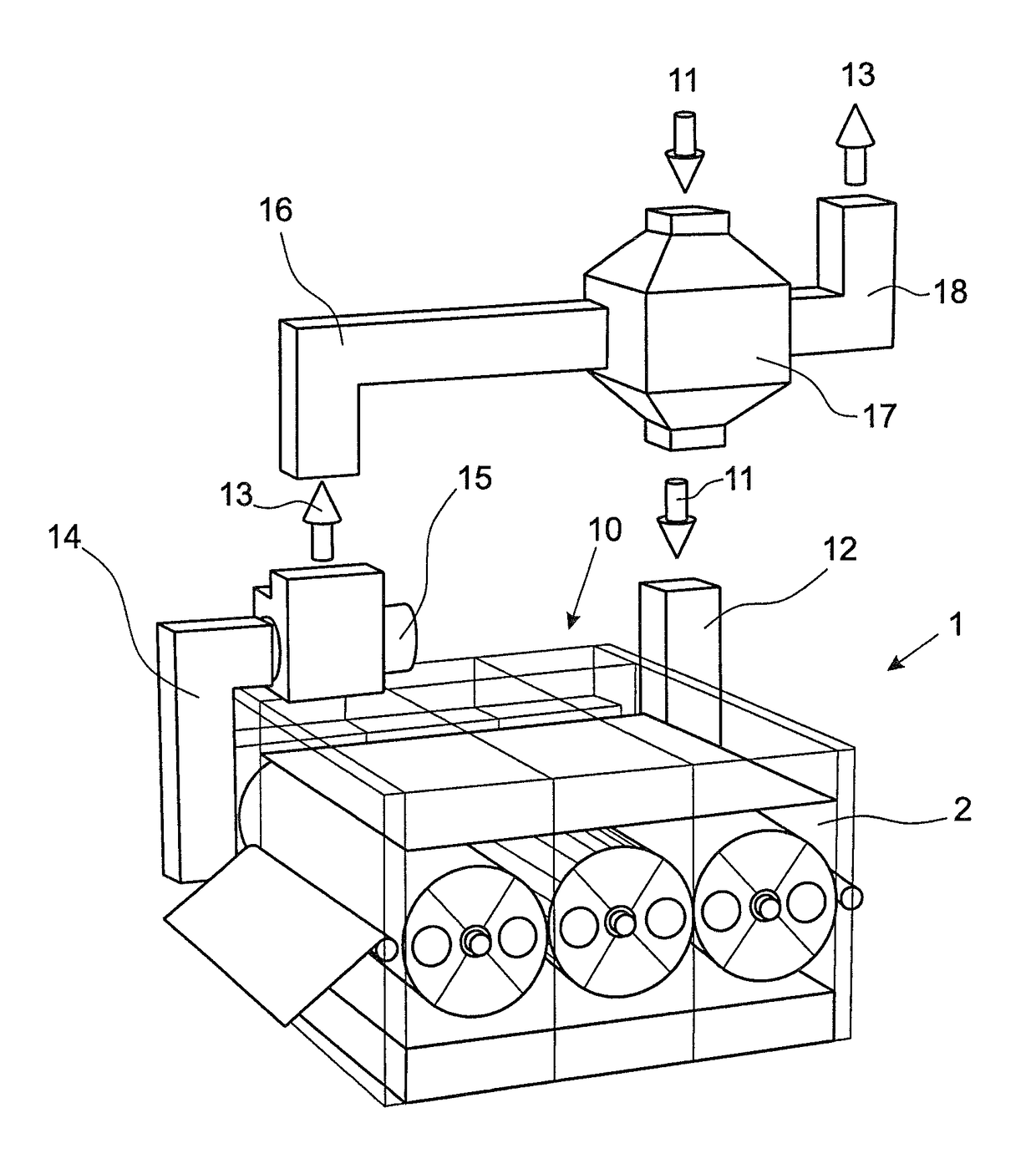
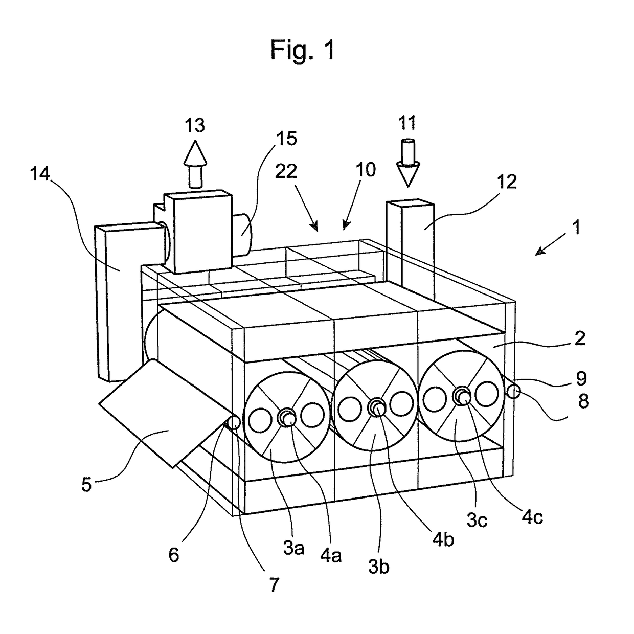
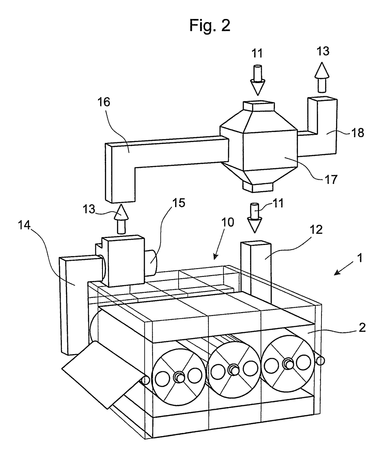
[0022]FIG. 1 shows a dryer 1 in the form of a serial dryer. Inside a dryer chamber 2, three drums 3a, 3b, 3c are arranged one after the other and with their axes 4a, 4b, 4c in a row. A fabric web 5 is guided into the dryer chamber 2 via an inlet 6. By means of a guide roller 7, the fabric web 5 is guided first under the first drum 3a, then above the second drum 3b and subsequently under the third drum 3c. By means of the guide roller 8, the fabric web 5 is guided out of the dryer chamber 2 through an outlet 9. Heated drying air flows through the fabric web 5 during its passage through the dryer chamber 2, the drying air absorbing the moisture of the fabric web 5 and being extracted via the interior of the drums 3a to 3c.

[0023]According to the invention, there is arranged at the dryer chamber 2 an additional compartment 10 into which the channel 12 for the fresh air 11 and the channel 14 for the exhaust air 13 open.

[0024]The additional compartment 10 is constructed so as to be fully...


PUM


Abstract

The invention relates to a dryer for a textile fabric web, comprising a dryer chamber (2) and having at least one drum (3a) which is arranged in the dryer chamber (2) and around at least part of which the fabric web (5) is wrapped, wherein heated drying air flows through the fabric web (5) and is discharged via an interior chamber of the drum (3a), characterized in that the dryer (1) has a separate additional compartment (10) via which fresh air (11) is supplied and exhaust air (13) is discharged.

Description

BACKGROUND OF THE INVENTION[0001]The invention relates to a dryer for a textile fabric web, and to a method of drying a textile fabric web.[0002]For drying textile fabric webs, dryers are known in which one or more drums are arranged in a housing. A textile fabric web is supplied to the dryer via an opening in the dryer compartment, the textile fabric web being wrapped around a large part of the periphery of the drum and then being discharged from the dryer compartment again. Usually, fresh air is also supplied via this opening, the fresh air being heated inside the dryer compartment and mixed with the circulating air in order to be able to absorb the greatest possible amount of moisture. While the fabric web is wrapped around the drum, the mixture of circulating air and fresh air flows through the fabric web, absorbs at least some of the moisture of the fibre web and is discharged again via the interior chamber of the drum. A volumetric sub-flow from this volumetric flow is dischar...

Claims


Application Information

Patent Timeline
Patent Type & Authority Patents(United States)
IPC IPC(8): F26B13/16F26B21/02
CPCF26B13/16F26B21/02
Inventor BOHN, MARKUSHAJDU, STEPHAN
Owner TRÜTZSCHLER GRP SE
Why Eureka
Try Eureka