
Dry ice blast cleaning system and method for operating the same

a technology of cleaning system and dry ice, which is applied in the direction of blast generating device, abrasive equipment, manufacturing tools, etc., can solve the problems of system affecting ambient atmospheric conditions, affecting the efficiency of use, and having a much longer shelf li

Active Publication Date: 2017-07-11
NU ICE AGE INC
View PDF25 Cites 7 Cited by
  • Summary
  • Abstract
  • Description
  • Claims
  • Application Information

AI Technical Summary

Benefits of technology

The patent describes a dry ice blast cleaning system with a heat by-pass system. The system includes a dry ice feed apparatus, a mixing head, a supply of pressurized gas, and a dispensing device. The hopper of the dry ice feeding apparatus has anti-bridging fingers to prevent clogging. The heat by-pass system includes a conduit and a regulator valve to control the amount of pressurized gas diverted to the mixing head. The amount of pressurized gas moved through the mixing head depends on the humidity in the air. The technical effects of the invention include improved cleaning efficiency, reduced clogging, and better control over the amount of pressurized gas used.

Problems solved by technology

Dry ice nuggets generally have a larger size than previously used dry ice pieces but have a much longer shelf life than smaller-sized forms of dry ice pieces available in the market.
The problem presented by the use of dry ice nuggets is that their size must be reduced for efficient use in a dry ice blast cleaning system.
One problem with conventional dry ice blast cleaning systems is that the systems are affected by ambient atmospheric conditions.
In particular, operation of the conventional dry ice blast cleaning systems can be difficult in environments having high humidity or where the cleaning requires prolonged storage of the dry ice pieces.
In such conditions, moisture in the ambient air in and around the system can condense around the dry ice pieces as liquid water or water ice, causing the dry ice pieces to adhere to one another and to clog the system.
The weld lines, specifically those in the lower portion of the hopper and those between the discharge end and the lower portion, can accumulate residue of the dry ice pieces, reducing the flow through of the dry ice pieces and clogging the lower portion.
In some cases, a user has been known to keep the dry ice blast cleaning system in an “ON” operating state, risking bodily harm and equipment damage while chiseling out the bridged dry ice pieces or dry ice residue.
Additionally, damage to the dry ice blast cleaning system may result from tools or debris falling into the hopper and into the mixing chamber.

Method used


Image

  • Dry ice blast cleaning system and method for operating the same
  • Dry ice blast cleaning system and method for operating the same
  • Dry ice blast cleaning system and method for operating the same

Examples


Embodiment Construction

[0021]Various embodiments of the present invention will be described in detail with reference to the drawings, where like reference numerals represent like parts and assemblies throughout the several views. Reference to various embodiments does not limit the scope of the invention. Additionally, any examples set forth in this specification are not intended to be limiting and merely set forth some of the many possible embodiments for the claimed invention.

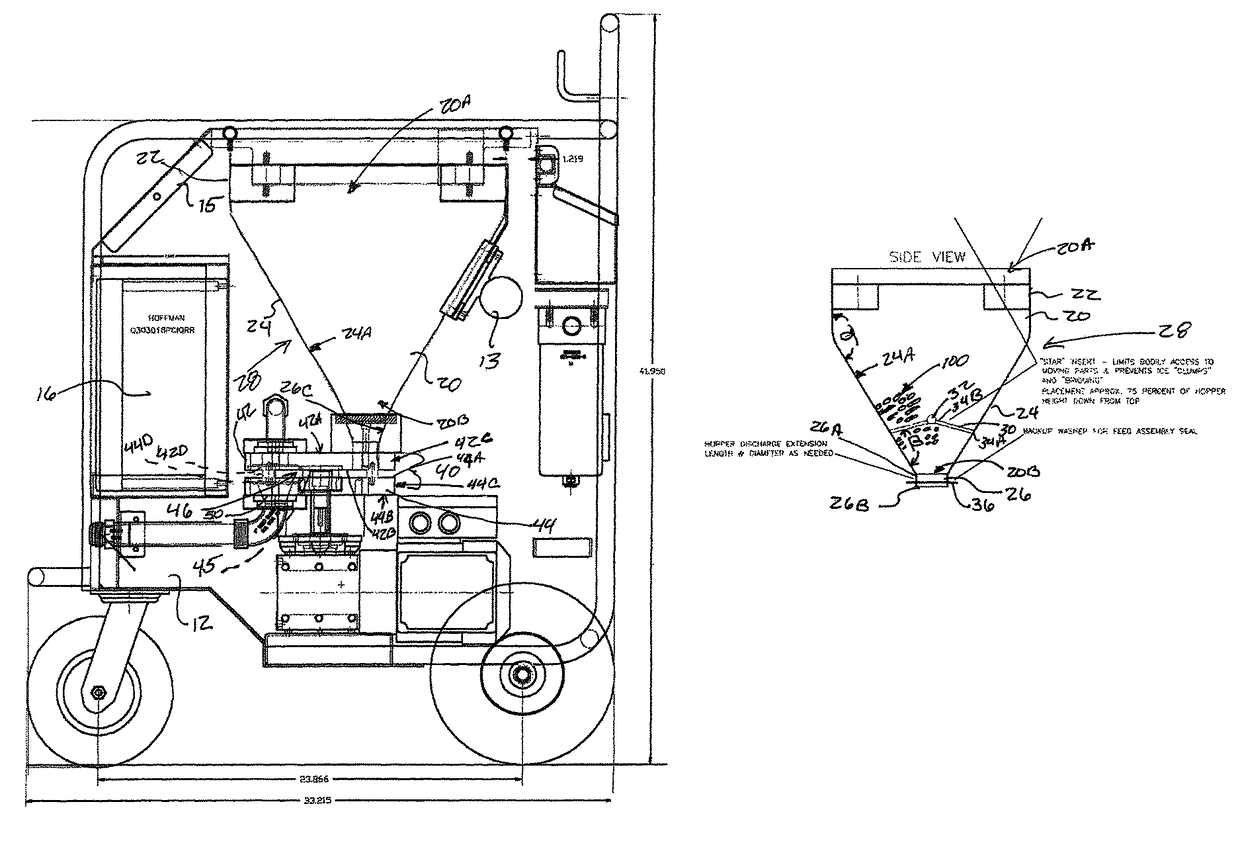
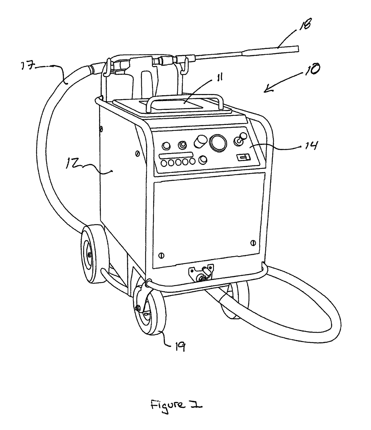
[0022]Referring now to the drawings, wherein the depictions are for the purpose of illustrating certain one embodiments only and not for the purpose of limiting the same, FIG. 1 shows a dry ice blast cleaning system 10 including a hose 17, a dispensing device 18, and housing 12 having the dry ice feed apparatus 28.

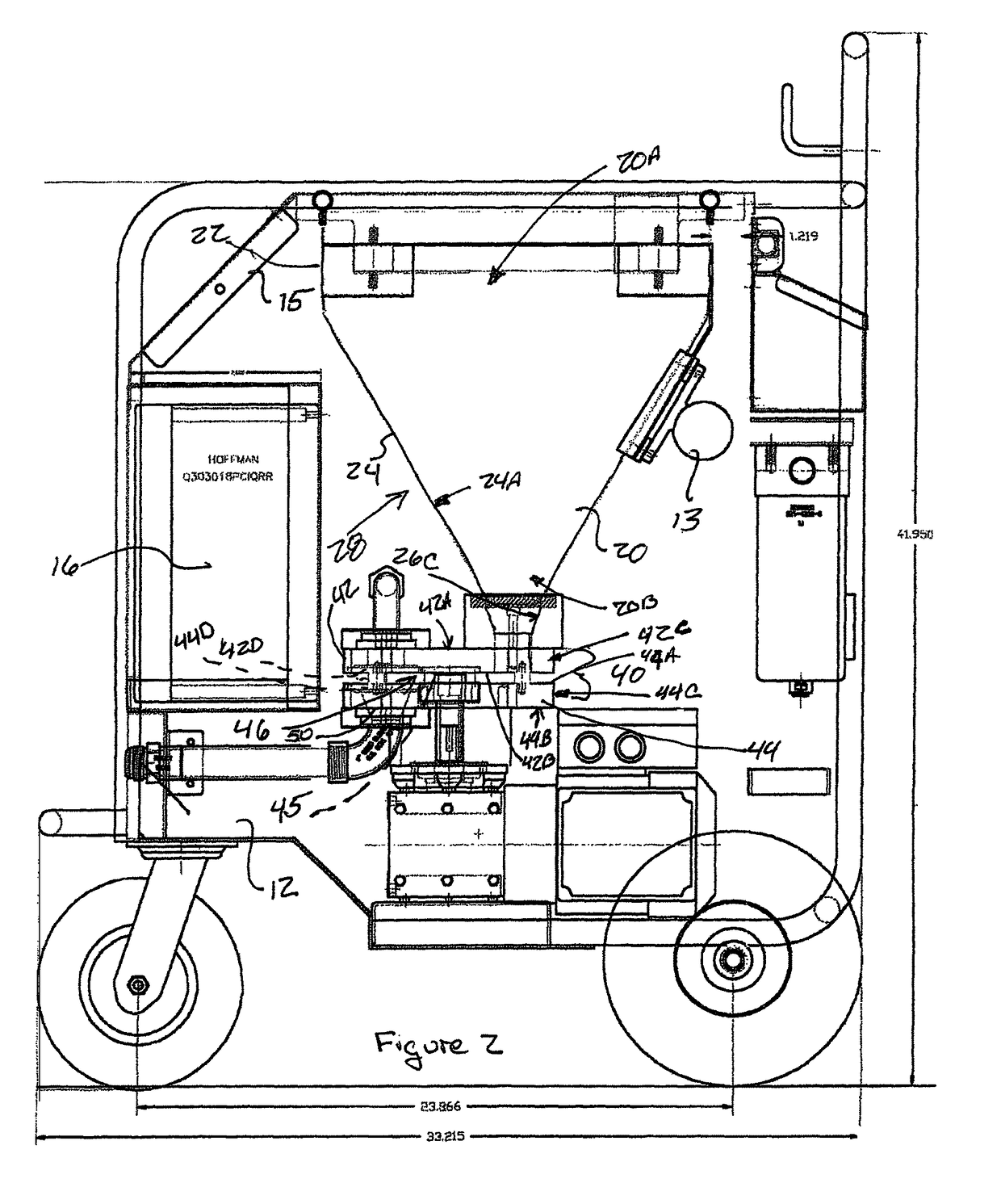
[0023]The dry ice blast cleaning system 10 includes a housing 12 configured to house the dry ice apparatus 28 including a hopper 20 or other dry ice storage container, a control system(s) 14, a supply of pressurized gas 16...


PUM


Abstract

A dry ice blast cleaning system is disclosed. The system includes a dry ice feed apparatus, a mixing head, a supply of pressurized gas and a dispensing device. The apparatus has a hopper configured to store a supply of dry ice pieces with an anti-bridging device. A heat by-pass system is provided to heat the mixing head to prevent icing in the mixing head.

Description

CROSS-REFERENCE TO RELATED APPLICATIONS[0001]Not ApplicableSTATEMENT REGARDING FEDERALLY SPONSORED RESEARCH OR DEVELOPMENT[0002]Not ApplicableREFERENCE TO SEQUENCE LISTING, A TABLE OR A COMPUTER PROGRAM LISTING COMPACT DISC APPENDIX[0003]Not ApplicableTECHNICAL FIELD[0004]This disclosure relates to the field of dry ice blast cleaning systems. More particularly, the present invention relates to a dry ice blast cleaning system having a dry ice feed apparatus and a method for feeding dry ice pieces within a dry ice blast cleaning system. More particularly, the present invention relates to a dry ice blast cleaning system having a heat by-pass system.BACKGROUND[0005]The statements in this section merely provide background information related to the present disclosure and may not constitute prior art.[0006]The use of dry ice for blast cleaning is well known in the art. In dry ice blast cleaning systems, pieces of dry ice (solidified Carbon Dioxide, CO2) are drawn into a fluid stream (typi...

Claims


Application Information

Patent Timeline
IPC IPC(8): B24C1/00B24C5/02B24C7/00
CPCB24C1/00B24C5/02B24C1/003B24C7/0069
Inventor COOPER, EDWARD LHALLENBECK, MICHAEL
Owner NU ICE AGE INC
Learn More