
Laser processing machine and focusing angle setting method of laser processing machine

a laser processing machine and laser processing technology, applied in the direction of optical elements, manufacturing tools, instruments, etc., can solve the problems of reducing processing quality, reducing the efficiency of laser marking machines, and small processing regions, so as to suppress the reduction of processing quality due to a variation of light spot areas, the effect of simple configuration

Active Publication Date: 2017-07-11
PANASONIC INDAL DEVICES SUNX
View PDF7 Cites 3 Cited by
  • Summary
  • Abstract
  • Description
  • Claims
  • Application Information

AI Technical Summary

Benefits of technology

The patent is for a laser marking machine that has a problem where the size of the light spot varies depending on the position on the surface being processed. This can result in uneven processing and lower quality. The patent proposes a solution using a focusing lens that can make the laser light shine on the surface vertically at any position, but this comes with its own limitations. Increasing the lens diameter to enlarge the processing region makes the machine expensive. The patent provides a solution to this problem that may improve processing quality and make the machine more affordable.

Problems solved by technology

Therefore, in the laser marking machine disclosed in JP-A-2009-208093, the light spot area varies depending on the position on a processing target surface, possibly lowering the processing quality.
However, with such a focusing lens, the processing region is made small because, in general, it enables vertical incidence of laser light only in a narrow range.
To enlarge the processing region, it is necessary to increase the lens diameter, which renders the laser marking machine expensive.
As a result, the laser processing machine is made complex in structure and hence expensive.

Method used


Image

  • Laser processing machine and focusing angle setting method of laser processing machine
  • Laser processing machine and focusing angle setting method of laser processing machine
  • Laser processing machine and focusing angle setting method of laser processing machine

Examples


embodiment

[0036]An embodiment of the present invention will be hereinafter described with reference to FIGS. 1-11.

[0037](1) Configuration of Laser Processing Machine

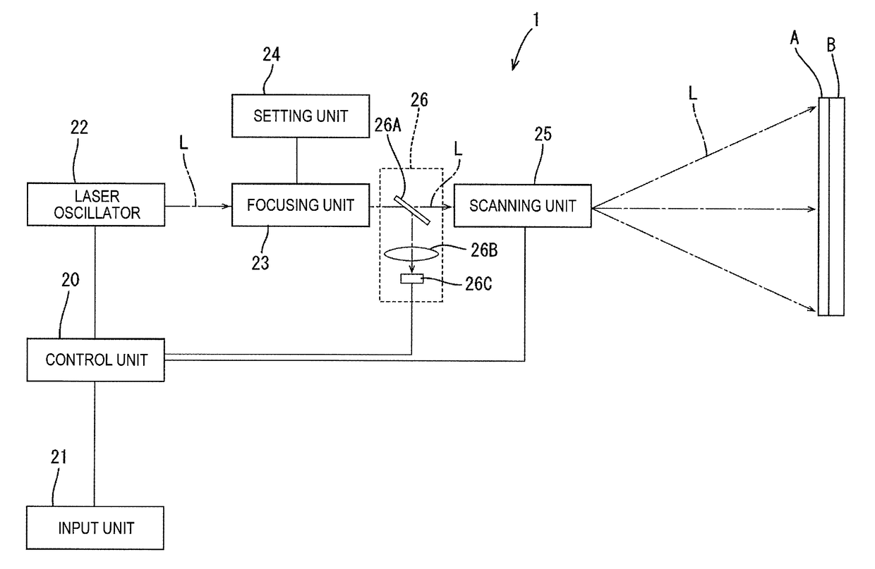
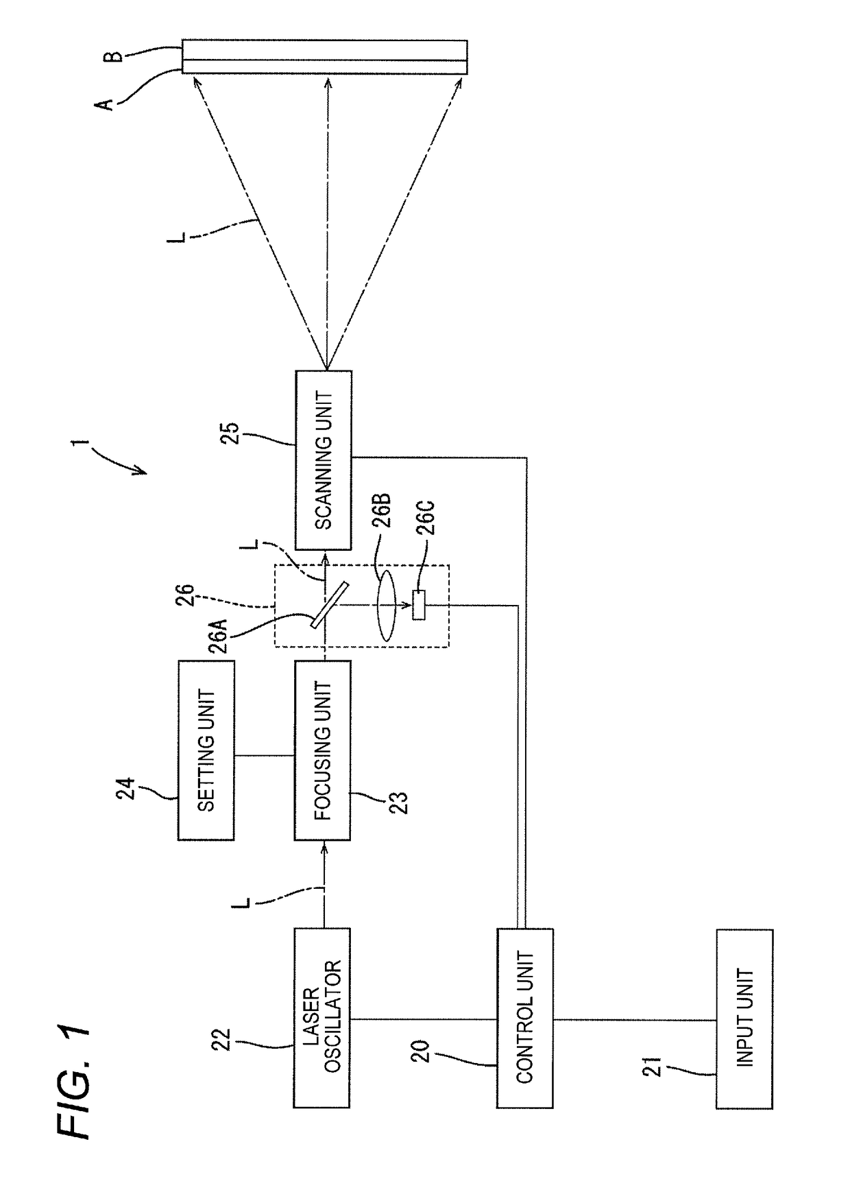
[0038]The configuration of a laser welding machine 1 which is a laser processing machine according to the embodiment will be described with reference to FIG. 1. The laser welding machine 1 is to weld two resin members A and B together by laser light. Whereas the resin member A is made of a material that transmits laser light almost completely, the resin member B is made of a material that absorbs laser light. When the resin member B melts absorbing laser light from the resin member A, the resin member A also melts receiving resulting heat, whereby the resin members A and B are welded together.

[0039]The laser welding machine 1 is equipped with a control unit 20, an input unit 21, a laser oscillator 22, a focusing unit 23, a setting unit 24, a scanning unit 25, a laser power monitoring unit 26, etc.

[0040]The control unit 20 is equip...


PUM

PropertyMeasurementUnit
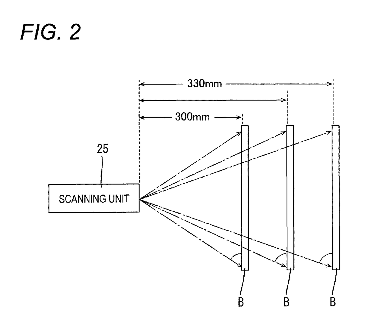
distanceaaaaaaaaaa
work distanceaaaaaaaaaa
areaaaaaaaaaaa

Abstract

A laser processing machine includes: a laser oscillator which emits laser light; a scanning unit which scans a processing target surface of a work by deflecting the laser light emitted from the laser oscillator; and a focusing unit which is disposed between the laser oscillator and the scanning unit and which focuses the laser light emitted from the laser oscillator. The focusing unit is set so as to focus the laser light at a second position that is more distant from a first position where the laser light is incident vertically than a third position that is farthest from the first position in the processing target surface of the work.

Description

CROSS-REFERENCE TO RELATED APPLICATION(S)[0001]This application is based on and claims priority from Japanese Patent Application No. 2015-110822 filed on May 29, 2015, the entire contents of which are incorporated herein by reference.BACKGROUND[0002]1. Field of the Invention[0003]One or more embodiments of the present invention relate to a laser processing machine for scanning the processing target surface of a work by deflecting laser light.[0004]2. Description of Related Art[0005]Among conventional laser processing machines that scan the processing target surface of a work by deflecting laser light emitted from a laser oscillator are ones in which a focal position of laser light can be set (refer to JP-A-2009-208093, for example). In a laser marking machine disclosed in JP-A-2009-208093, a focal position setting means is disposed between a laser light source and a scanning unit and a focusing lens is disposed between the scanning unit and a work. A focal position is set by changin...

Claims


Application Information

Patent Timeline
Patent Type & Authority Patents(United States)
IPC IPC(8): G02B26/08G02B27/40B23K26/06H01S3/00B23K26/082G02B26/10H01S3/13B29C65/16B29C65/00
CPCG02B27/40B23K26/0648B23K26/082G02B26/105H01S3/005B29C65/1635B29C65/1654B29C66/1122B29C66/41H01S3/1305B23K26/046
Inventor MIYAZAKI, TAKAYOSHIKOMIYA, TOMOKIYOSHIMI, TAKUYA
Owner PANASONIC INDAL DEVICES SUNX
Learn More