Modular electronic system

a technology of electronic systems and modules, applied in the direction of electrical apparatus construction details, instruments, support structure mounting, etc., can solve the problems of individual and thus cost-intensive components, difficult installation of heat sinks and fans, and inability to optimally solve cooling problems of electronic modules, etc., to achieve reliable and stably connected with each other

Inactive Publication Date: 2017-07-11
WAGO VERW GMBH
View PDF14 Cites 0 Cited by
  • Summary
  • Abstract
  • Description
  • Claims
  • Application Information

AI Technical Summary

Benefits of technology

[0015]The system according to the invention comprises a layered structure composed of several electronic modules with an air inlet- and air outlet opening for heat management, respectively. The electronic module to be cooled is adjacent to opposite sides on two adjacent electronic modules in this arrangement. The electronic modules according to the invention are designed that air can enter into a first adjacent (e.g. lower) electronic module, absorb the heat of the electronic components in the air space of the electronic module to be cooled and exit heated from a second adjacent (e.g. upper) electronic module. Thus, the height difference between the air inlet and the air outlet is increased in a horizontal installation position, which leads to the generation of an air stream within the (intermediate) electronic module to be cooled in a reliable manner as a result of natural convection, which cools this electronic module. Thus, the thereby generated cooling air duct is not just limited to the single electronic module, but is extended by the adjacent electronic modules, which decisively improves the thermal convection.
[0037]There are also the above described advantages of an improved cooling management of a modular electronic system. Thus, particularly, additional cooling elements such as fans or heat sinks are avoided.

Problems solved by technology

However, the electronic modules are comparably small in many applications in the field of control technology, for example they are just a few millimeters wide, so that an installation of heat sinks and fans is very difficult.
However, the cooling of the electronic modules remains a problem that has not been optimally solved yet.
Said heat management-solutions of the prior art require individual and thus cost-intensive components, such as for example particular heat sinks.
Here, in particular the problem arises that the single modules of such a system comprise just small exposed exterior surfaces which can dissipate heat.
Thus, solutions with heat sinks are not suitable.

Method used


Image

  • Modular electronic system
  • Modular electronic system
  • Modular electronic system

Examples


Embodiment Construction

[0045]In the following preferred embodiments of the present invention are described with reference to the accompanying figures. Features of single embodiments can be combined with those of other embodiments, as well, although such combinations are not illustrated in the individual case in detail.

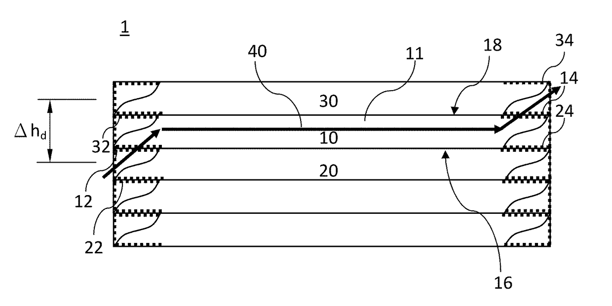
[0046]FIG. 1 shows a modular electronic system 1 according to the invention with a multilayer structure of electronic modules 10, 20, 30. The electronic system 1 comprises five electronic modules 10, 20, 30 in the illustrated example. Each of the electronic modules 10, 20, 30 comprises and air inlet opening 12, 22, 32 and an air outlet opening 14, 24, 34.

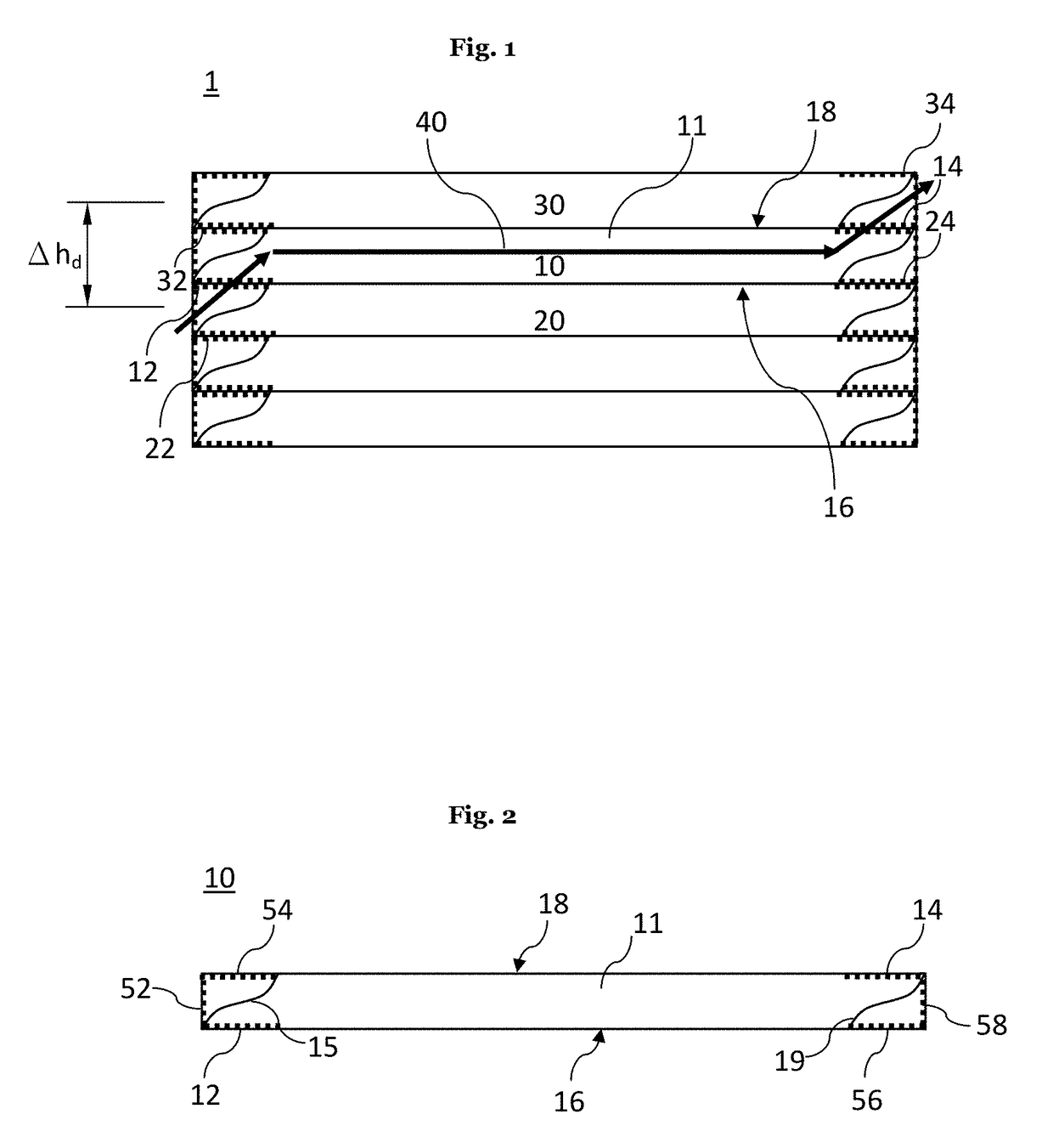
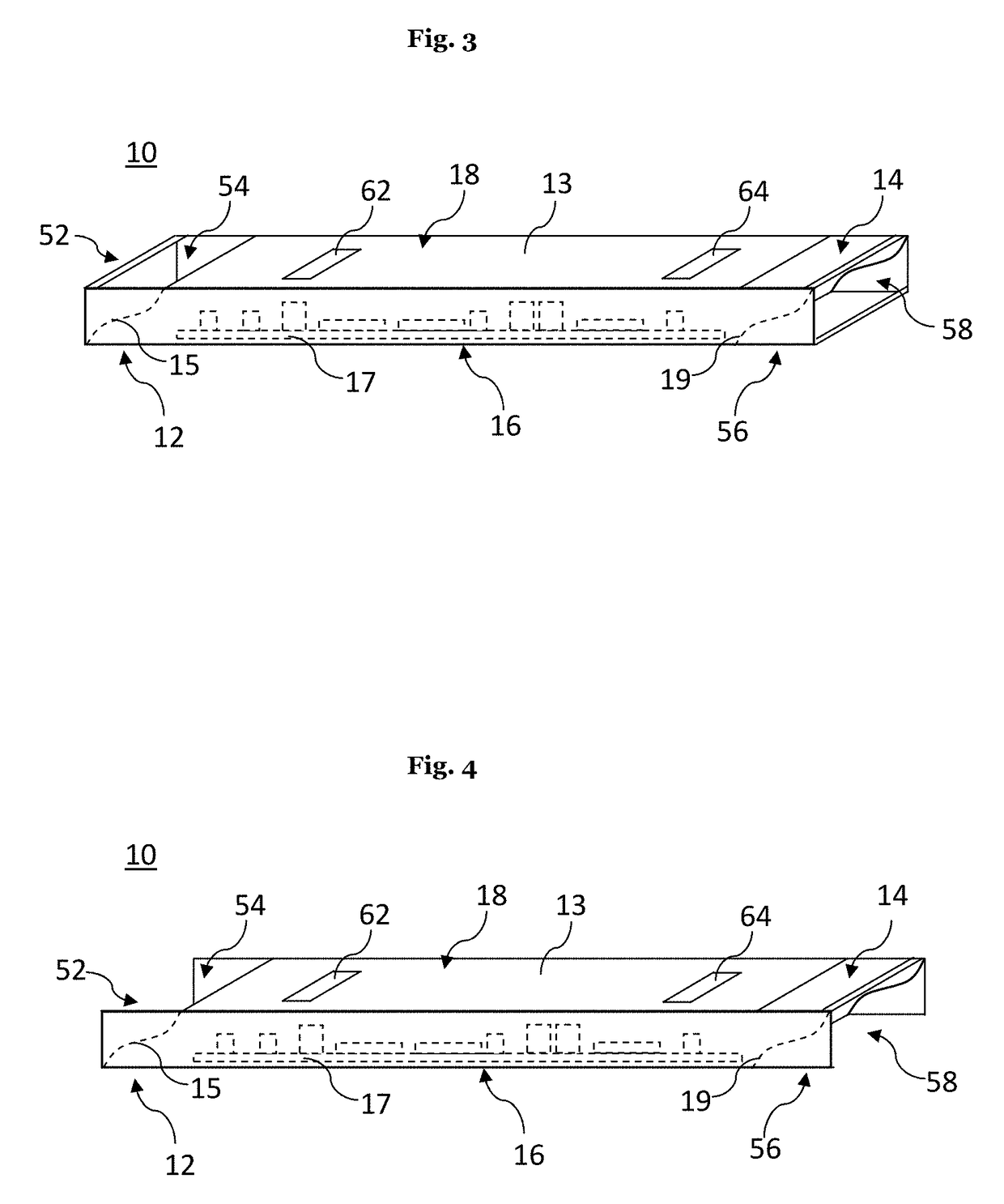
[0047]Preferably, an electronic module 10, 20, 30 comprises at least one circuit board 17 with electronic components or component parts and contacts for electronic connection, which are not illustrated.

[0048]The electronic modules 10, 20, 30 further comprise a housing 13, which surrounds the circuit board 17 with the electronic components. T...


PUM


Abstract

Modular electronic system 1 with convection cooling, comprising a plurality of electronic modules 10, 20, 30, that each comprise an air inlet opening 12, 22, 32, an air outlet opening 14, 24, 34 and an air space 11 within the electronic module 10, 20, 30, wherein the air space 11 is in air exchange with the air inlet opening 12, 22, 32 and the air outlet opening 14, 24, 34, wherein at least one of the electronic modules 10, 20, 30 is an electronic module to be cooled 10, one of the electronic modules 10, 20, 30 is a first adjacent electronic module 20, which is adjacent to a first side 16 of the electronic module to be cooled 10 and one of the electronic modules 10, 20, 30 is a second adjacent electronic module 30, which is adjacent to a second side 18 opposite to the first side 16 of the electronic module to be cooled 10, wherein the electronic modules 10, 20, 30 are designed in such a manner that air can enter into the first adjacent electronic module 20, generate an air stream 11 for cooling within the air space 11 of the electronic module to be cooled 10 and exit heated from the second adjacent electronic module 30.

Description

[0001]This application claims priority of German Application No. 10 2014 201 483.2 filed Jan. 28, 2014, which is hereby incorporated herein by reference.FIELD OF THE INVENTION[0002]The present invention relates to a modular electronic system with convection cooling.BACKGROUND[0003]Electronic modules, in particular in the control technology, comprise circuit boards, so called “printed circuit boards” which are used for electronic connection and mechanical fixation of electronic components. These circuit boards are often used in small housings in the control technology, which protect the electronics arranged therein and serve as fixation.[0004]The electronic components are usually densely packed within the electronic modules for reasons of space. However, the electronic components of the electronic modules generate heat by their electrical power, which has to be dissipated so that no overheating of the electronic modules follows. Thus, a heat management is necessary in the electronic ...

Claims


Application Information

Patent Timeline
Patent Type & Authority Patents(United States)
IPC IPC(8): H05K7/20H01L23/467H01L23/427H05K7/14G06F1/20
CPCH05K7/20127H01L23/427H01L23/467H05K7/1465G06F1/20
Inventor HENKEL, MARCO
Owner WAGO VERW GMBH
Why Eureka
Try Eureka