
Synchronous rectification circuit adapted to electronic transformer and switching power supply thereof

Active Publication Date: 2017-07-18
SILERGY SEMICON TECH (HANGZHOU) CO LTD
View PDF10 Cites 3 Cited by
  • Summary
  • Abstract
  • Description
  • Claims
  • Application Information

AI Technical Summary

Benefits of technology

The patent text describes a synchronous rectification circuit that adjusts the operation of transistor switches to improve efficiency and reduce size. This circuit integrates transistor switches from a rectifier bridge and a switching control circuit onto a single chip. The technical effect of this synchronous rectification is improved performance and reduced size of the circuit.

Problems solved by technology

Although the rectifier bridge has a low cost, it has a large size and causes a power loss which in turn decreases power efficiency.

Method used


Image

  • Synchronous rectification circuit adapted to electronic transformer and switching power supply thereof
  • Synchronous rectification circuit adapted to electronic transformer and switching power supply thereof
  • Synchronous rectification circuit adapted to electronic transformer and switching power supply thereof

Examples


Embodiment Construction

[0029]Reference will now be made in detail to particular embodiments of the disclosure, examples of which are illustrated in the accompanying drawings. While the disclosure will be described in conjunction with the preferred embodiments, it will be understood that they are not intended to limit the disclosure to these embodiments. On the contrary, the disclosure is intended to cover alternatives, modifications and equivalents that may be included within the spirit and scope of the disclosure as defined by the appended claims. Furthermore, in the following detailed description of the present disclosure, numerous specific details are set forth in order to provide a thorough understanding of the present disclosure. However, it will be readily apparent to one skilled in the art that the present disclosure may be practiced without these specific details.

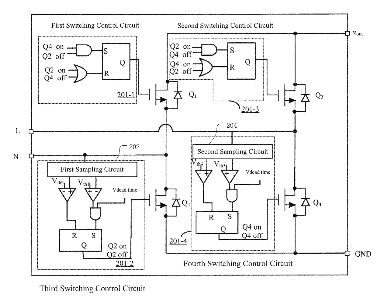
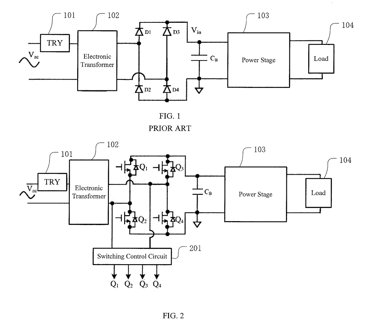
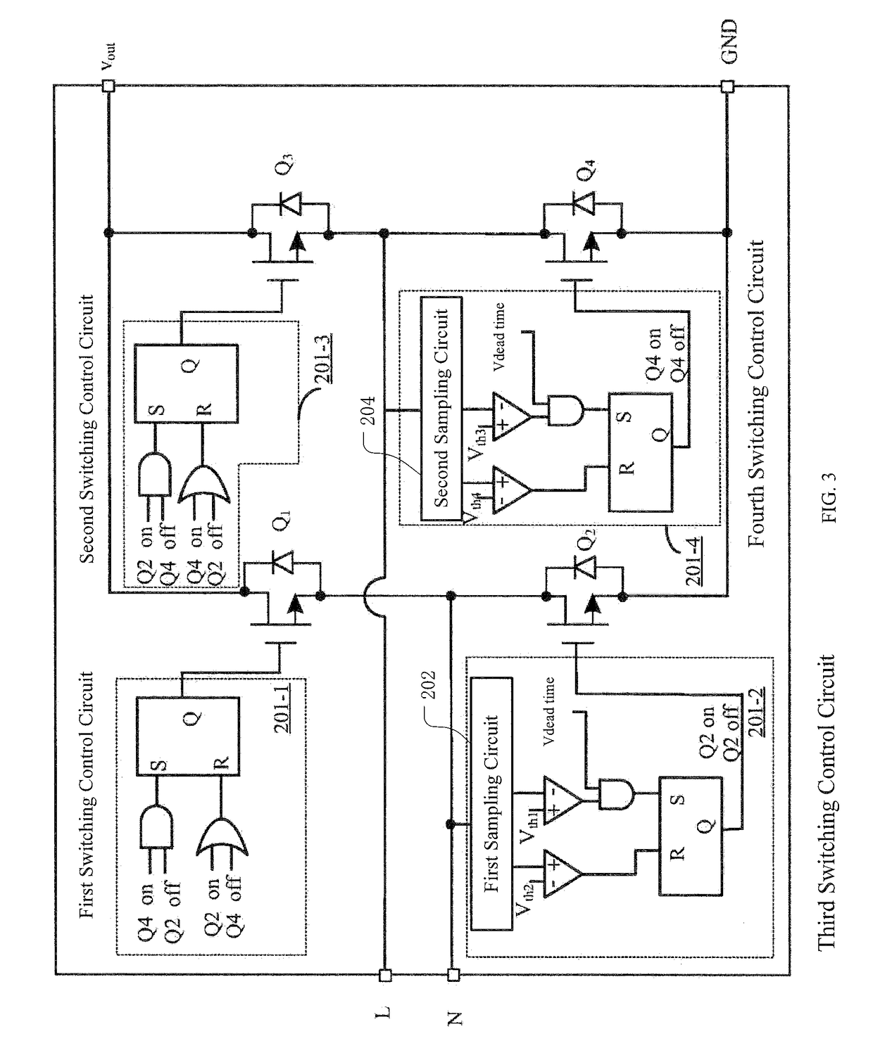
[0030]Referring now to FIG. 2, a schematic diagram of an example synchronous rectification circuit adapted to an electronic transformer ...


PUM


Abstract

The present disclosure relates to a synchronous rectification circuit adapted to an electronic transformer. Operation states of four transistor switches in the synchronous rectification circuit are adjusted in accordance with a detected input voltage signal of the synchronous rectification circuit to achieve synchronous rectification. Moreover, the transistor switches in a rectifier bridge and a switching control circuit are all integrated into a single chip to have an increased integration level, a reduced chip size, and high efficiency. The present disclosure also relates to a switching power supply comprising the above synchronous rectification circuit.

Description

CROSS-REFERENCE TO RELATED APPLICATION[0001]This application claims the benefit of Chinese Patent Application No. 201310514284.1, filed on Oct. 25, 2013, which is incorporated herein by reference in its entirety.TECHNICAL FIELD[0002]The present disclosure generally relates to the field of power electronics, and more particularly, to a synchronous rectification circuit adapted to an electronic transformer and a switching power supply thereof.BACKGROUND[0003]In a conventional switching power supply, an AC input voltage is typically rectified by a rectifier bridge, such as a full bridge or a half bridge. FIG. 1 illustrates a schematic diagram of a rectifier bridge used in a switching power supply. The rectifier bridge, for example, a full bridge, includes four diodes D1, D2, D3 and D4 which are connected with each other as an electrical bridge and packaged as a chip. In a rectification cycle, the diodes D1 and D4 conduct during a positive half sine wave, and the diodes D2 and D3 conduc...

Claims


Application Information

Patent Timeline
IPC IPC(8): H02M7/217H02M7/219H02M1/38H02M1/08
CPCH02M7/219H02M1/08H02M1/38H02M2007/2195Y02B70/1408H02M7/2195Y02B70/10
Inventor ZHANG, LINGDONG
Owner SILERGY SEMICON TECH (HANGZHOU) CO LTD
Learn More