Lighting arrangement

a technology of lighting arrangement and led chip, applied in the direction of fixed installation, lighting and heating equipment, instruments, etc., can solve the problems of reducing overall brightness, affecting the effect of lighting arrangement, and affecting the perception of led chip light, etc., and achieves effective and reliable lighting arrangement. good

Active Publication Date: 2017-07-25
KONINK PHILIPS ELECTRONICS NV
View PDF23 Cites 14 Cited by
  • Summary
  • Abstract
  • Description
  • Claims
  • Application Information

AI Technical Summary

Benefits of technology

[0011]An advantage of the lighting element according to the invention is that it can be realised in a very compact manner, since the spreading element can be arranged very close to the light source. No additional reflecting or collecting elements are needed to direct the light into any outer regions of the collecting plane, since this effect can be achieved entirely by the lighting element itself. Furthermore, the light spread over the collecting plane exhibits a favourable uniform quantity of light per unit area, making such a lighting element particularly suited for use in applications that require a non-circular light source shape with even or uniform light distribution.
[0013]An advantage of the light redirecting element according to the invention is that it can be placed in the collecting plane of a lighting arrangement of the type described above, to optimally collect the spread light and to direct it outward towards an observer, giving the appearance of a longitudinal light source with a favourably even or uniform appearance.
[0017]The dimensions of the longitudinal planar emission face are preferably chosen to complement the dimensions of the spreading element and its spreading plane. Therefore, in a particularly preferred embodiment of the invention, a length of the emission face exceeds a width of the emission face by a factor of at least 3, more preferably by a factor of at least 6; most preferably by a factor of at least 10, i.e. the aspect ratio of the emission face is at least 1:3, more preferably at least 1:6, most preferably at least 1:10. The planar emission face therefore provides a light source shape that is favourably long and narrow, making the lighting arrangement particularly suitable for lighting applications that require a long, narrow and uniform light source shape.
[0019]The spreading element itself can provide a favourable spreading effect for a light source such as a top-emitting LED chip. LED chips that also emit to the side are also available. Therefore, in a particularly preferred embodiment of the invention, the lighting element comprises a receptacle for containing the light source, which receptacle comprises a reflective outer surface, and wherein the receptacle and the spreading element are realised to obtain a light output distribution comprising a first lateral spread portion in a first half of the spreading plane to one side of the optical axis, and a second lateral spread portion in the other half of the spreading plane, wherein a lateral spread portion of the radiation angle pattern is bounded by a first angle subtended from the optical axis and a second angle subtended from the optical axis. The receptacle or “cup” is specifically shaped and finished to guide any light emitted from the sides of the LED chip outward to obtain the desired radiation angle pattern. Preferably, the receptacle or cup is shaped as a recess with one or more sloping faces, arranged according to the arrangement of lobes. For example, a receptacle with an essentially rectangular perimeter can comprise a sloping face on each side of a square or rectangular LED chip. Such a receptacle can comprise a long or “major” sloping face with a shallow inclination that extends some distance under a lobe of the spreading element. The receptacle can also comprise a “minor” sloping face on each of the two remaining sides of the LED chip, preferably with a steep inclination. Alternatively, a receptacle with an essentially rectangular perimeter can comprise two long “major” sloping faces as described above, while the remaining two sides are essentially vertical. Such a combination of long, shallowly inclined receptacle surfaces and short, steeply inclined side faces, together with the light-refracting function of the “peanut”, can achieve the desired wide and simultaneously narrow spreading plane or spreading “slice”. The angle of a major sloping face is preferably chosen according to the desired spreading effect. Evidently, a flatter angle will result in a more lateral spreading of the light in the spreading plane, and a correspondingly “longer” aspect ratio, whereas a steeper angle will result in a more compact spreading of the light in the spreading plane, and a correspondingly “shorter” aspect ratio.
[0023]Since the light is spread on both sides of the “peanut”, this light distribution or radiation angle pattern has the appearance of a “batwing”, as will be shown in the description of the drawings. The “batwing” distribution between these angles in the spreading plane ensures an essentially uniform quantity of light per unit area at the collecting plane. In another preferred embodiment of the invention, the lighting element is realised to spread the light in the spreading plane such that losses in the light redirecting element may be compensated for. For example, light in the outer reaches of the spreading plane will need to be bent or manipulated by the light redirecting element, to a greater extent than, for example, light that is emitted closer to the optical axis, which undergoes less bending or manipulating as it passes through the light redirecting element. The secondary losses occurring during light transmission through the outer ends of the light redirecting element are preferably compensated for in advance by realising the lighting element to direct more light into the relevant outer reaches of the spreading plane. For example, for a lighting element intended to emit the greater portion of its light into angular regions between 65° and 75° on each side of its optical axis, the “peanut” and / or the reflective cup of the lighting element can be shaped to direct additional light into the region bounded by 73.5° and 75°. In this way, a favourably homogenous light distribution can be achieved all along the longitudinal planar emission face of the light redirecting element.
[0024]The light in the spreading plane is collected by a light redirecting element relatively close to the lighting element, so that the spread light is collected at a level in which the spread light can provide the appearance of a rectangular or longitudinal “light source” of the desired dimensions. To this end, the light redirecting element can be positioned directly above the spreading element, at a slight distance from the spreading element, or at a greater distance from the spreading element, depending on the desired effect.

Problems solved by technology

A disadvantage of an LED is that the light emitted from the small area of the LED chip is perceived as a small, bright point of light.
However, some of the light can be lost in this way, and the overall brightness is diminished.
To better achieve the impression of a single light source, such lighting arrangements require diffusers or dedicated lenses to collect, refract and re-combine the light in the desired distribution, whereby such optical elements are always associated with some degree of loss.
Furthermore, failure of one of an array of light sources will result in a “hole” in the overall light arrangement.
Clearly, such an uneven light distribution over the light source shape is unfavourable and even unacceptable for certain lighting applications that require an overall even brightness.
However, these manipulations result in losses and in a reduction of the overall light output, so that such arrangements are unfavourably inefficient.
Also, these arrangements are complicated, bulky and expensive.

Method used


Image

  • Lighting arrangement
  • Lighting arrangement
  • Lighting arrangement

Examples


first embodiment

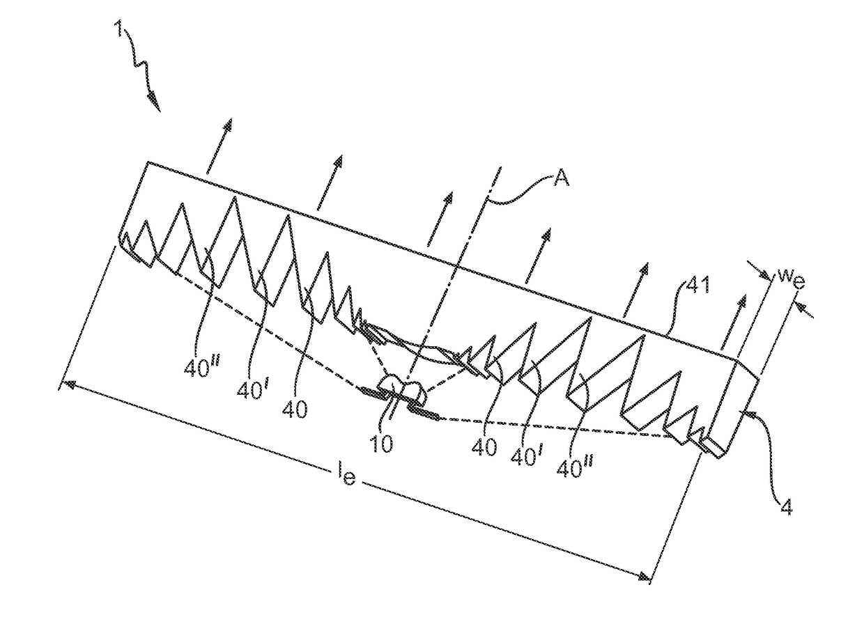
[0047]FIG. 6 shows a lighting arrangement 1 according to the invention. Here, the lighting element 10 is arranged below a Fresnel lens element 4, comprising a body with a plurality of lateral refracting prism elements 40, 40′, 40″, a central refracting portion, and an essentially rectangular emission face 41. The Fresnel lens element 4 is preferably formed in one piece, for example by an extrusion or milling process. The light emitted by the lighting element 10 is spread outward by the double-lobed spreading element such that a “batwing” characteristic is predominantly obtained, indicated here by the broken lines. The lateral refracting prism elements 40, 40′, 40″ are shaped to collect the light of various sectors of the “batwing” and refract the collected light essentially perpendicularly outward from the emission face 41 of the Fresnel lens 4. To an observer looking at the emission face 41, therefore, this appears as a uniform rectangular source of light with a length le and width...

second embodiment

[0049]FIG. 8 shows a lighting arrangement 1′ according to the invention. Here, the lighting element 10 is arranged below a translucent strip 5 that is coated with or otherwise treated to comprise a phosphor layer, indicated by the stippled pattern. The phosphor layer is illuminated by the batwing distribution of the light spread by the lighting element 10 when the enclosed LED is driven by a voltage across its electrodes. Since the phosphor collects the incident light and re-emits or scatters the light essentially uniformly according to the Lambert cosine law, i.e. the phosphor layer acts as an isotropic radiator, the effect of this lighting arrangement 1′ is to provide an evenly “emitting” surface 5 that itself appears to act as a light source 5. The light collected and emitted by the phosphor from a point on the translucent strip 5 is indicated here by groups of light rays emitted essentially uniformly in all directions. Such a lighting arrangement 1′ can be used to good effect to...


PUM


Abstract

Lighting arrangement (1, 1′) comprising a light source (2) for generating light; a spreading element (3) realized to laterally spread the generated light in a spreading plane (S), defined by an optical axis (AO) of the light source (2) and a longitudinal axis (L) of the spreading element (3), to give an essentially uniform quantity of light per unit area at an emission face (41, 51) orthogonal to the spreading plane (S) and parallel to the longitudinal axis (L) of the spreading element (3) and a light redirecting element (4, 5) arranged to collect the spread light, which comprises a longitudinal planar emission face (41, 51), and is realized to collect the laterally spread light and to emit the collected light essentially uniformly from the emission face (41, 51).

Description

CROSS-REFERENCE TO PRIOR APPLICATIONS[0001]This application is the U.S. National Phase application under 35 U.S.C. §371 of International Application No. PCT / IB2013 / 053188, filed on Apr. 23, 2013, which claims the benefit of U.S. Provisional Patent Application, No. 61 / 638,521, filed on Apr. 26, 2012. These applications are hereby incorporated by reference herein.FIELD OF THE INVENTION[0002]The invention describes a lighting arrangement, a lighting element, a light redirecting element, and a number of lighting units.BACKGROUND OF THE INVENTION[0003]With developments in light-emitting diode (LED) technology, lighting solutions that comprise LEDs instead of conventional light bulbs are becoming more popular. An LED comprises a semiconductor diode chip that emits light from an emitter surface. The emitter surface area is very small, usually in a region of only a few square millimeters, sometimes even only a few hundredths of a square millimeter. Such an LED chip can be a top-emitting dev...

Claims


Application Information

Patent Timeline
Patent Type & Authority Patents(United States)
IPC IPC(8): F21K99/00F21K9/60F21V8/00F21V5/04F21V13/04F21S8/10F21Y115/10
CPCF21V5/045F21K9/60F21S48/00F21S48/2243F21S48/2262F21S48/2268F21S48/2281F21S48/2287F21V13/04G02B6/0016F21S48/215F21Y2115/10G02B6/003G02B6/0028F21Y2101/00F21S43/14F21S43/239F21S43/243F21S43/245F21S43/247F21S43/249F21K9/27F21S43/16F21V5/10H01L33/58F21V5/04
Inventor SPINGER, BENNOMARTIN, PAUL SCOTTBLOEMEN, PASCAL JEAN HENRITAI, KUOCHOU
Owner KONINK PHILIPS ELECTRONICS NV
Why Eureka
Try Eureka