
Spark plug

a spark plug and spark plug technology, applied in the direction of spark plugs, electrical devices, electric discharge tubes, etc., can solve the problems of increasing the cost of the entire ignition system, and achieve the effects of reducing the flame quenching effect of the center electrode, and increasing the ignitability of the spark plug

Active Publication Date: 2017-07-25
NGK SPARK PLUG CO LTD
View PDF22 Cites 0 Cited by
  • Summary
  • Abstract
  • Description
  • Claims
  • Application Information

AI Technical Summary

Benefits of technology

This patent describes a spark plug with a recess on the side of the plug that helps increase its ignitability. This recess prevents the temperature of the plug from getting too high and reduces the flame quenching effect, which inhibits ignition. The recess is formed in a melted portion of the plug and can be easily formed. This design improves the performance of the spark plug without adding any complexity to its structure. Additionally, the projection may have multiple recesses, which further enhances the ignitability of the plug. Overall, this design allows for a better controlled ignition and improved performance of the spark plug.

Problems solved by technology

However, to increase the ignition energy, an ignition coil or the like capable of generating a large amount of energy is required, and therefore the cost of the entire ignition system is increased.

Method used


Image

  • Spark plug
  • Spark plug
  • Spark plug

Examples


embodiment

A. Embodiment

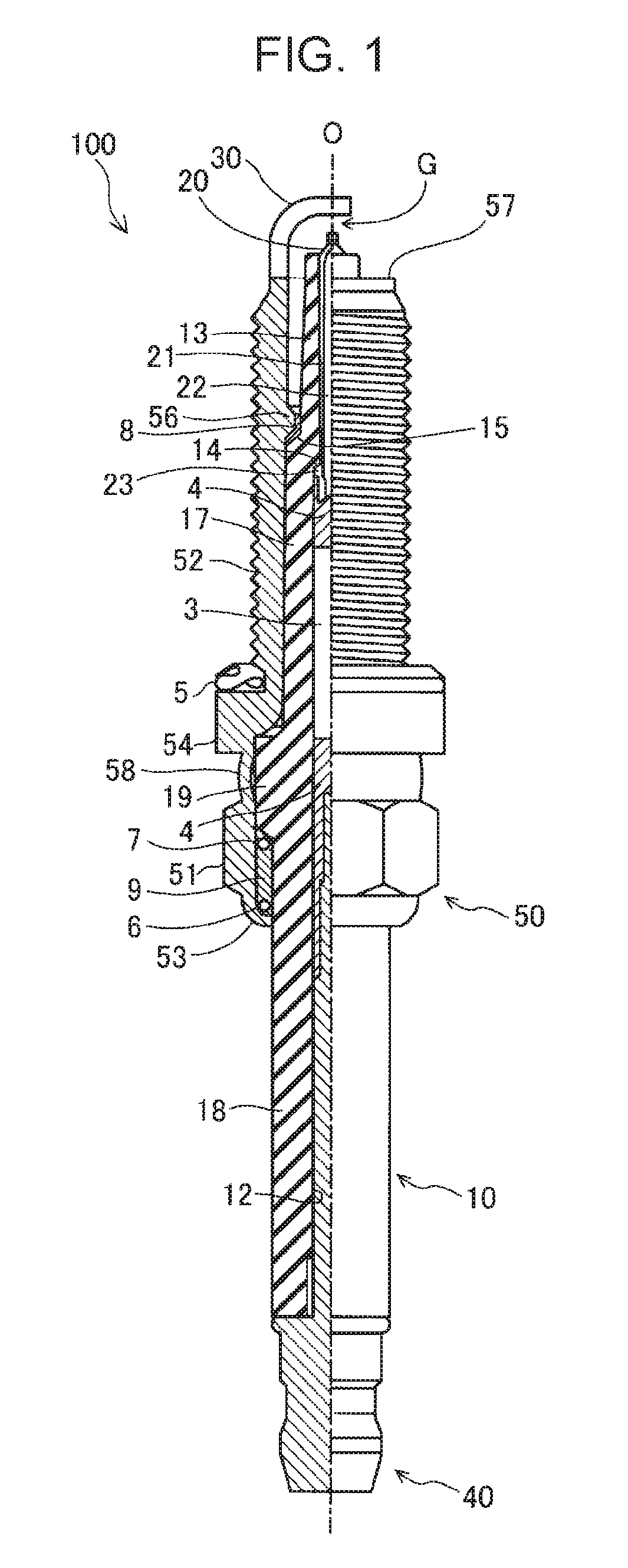
[0025]FIG. 1 is a partially sectioned view of a spark plug 100 according to an embodiment of the present invention. The spark plug 100 has a thin long shape that extends along an axial line O. In FIG. 1, an external front view of the spark plug 100 is shown on the right side of the axial line O, which is represented by the dotted chain line, and a sectional view of the spark plug 100 along the axial line O is shown on the left side of the axial line O. In the following description, the upper side of FIG. 1 is referred to as the front side of the spark plug 100, and the lower side of FIG. 1 as the rear side of the spark plug 100.

[0026]The spark plug 100 includes an insulator 10, a center electrode 20, a ground electrode 30, and a metal shell 50. The insulator 10 has an axial hole 12 that extends along the axial line O, and at least a portion of the periphery of the insulator 10 is held by a metal shell 50 having a tubular shape. The center electrode 20 is disposed in the...

first modification

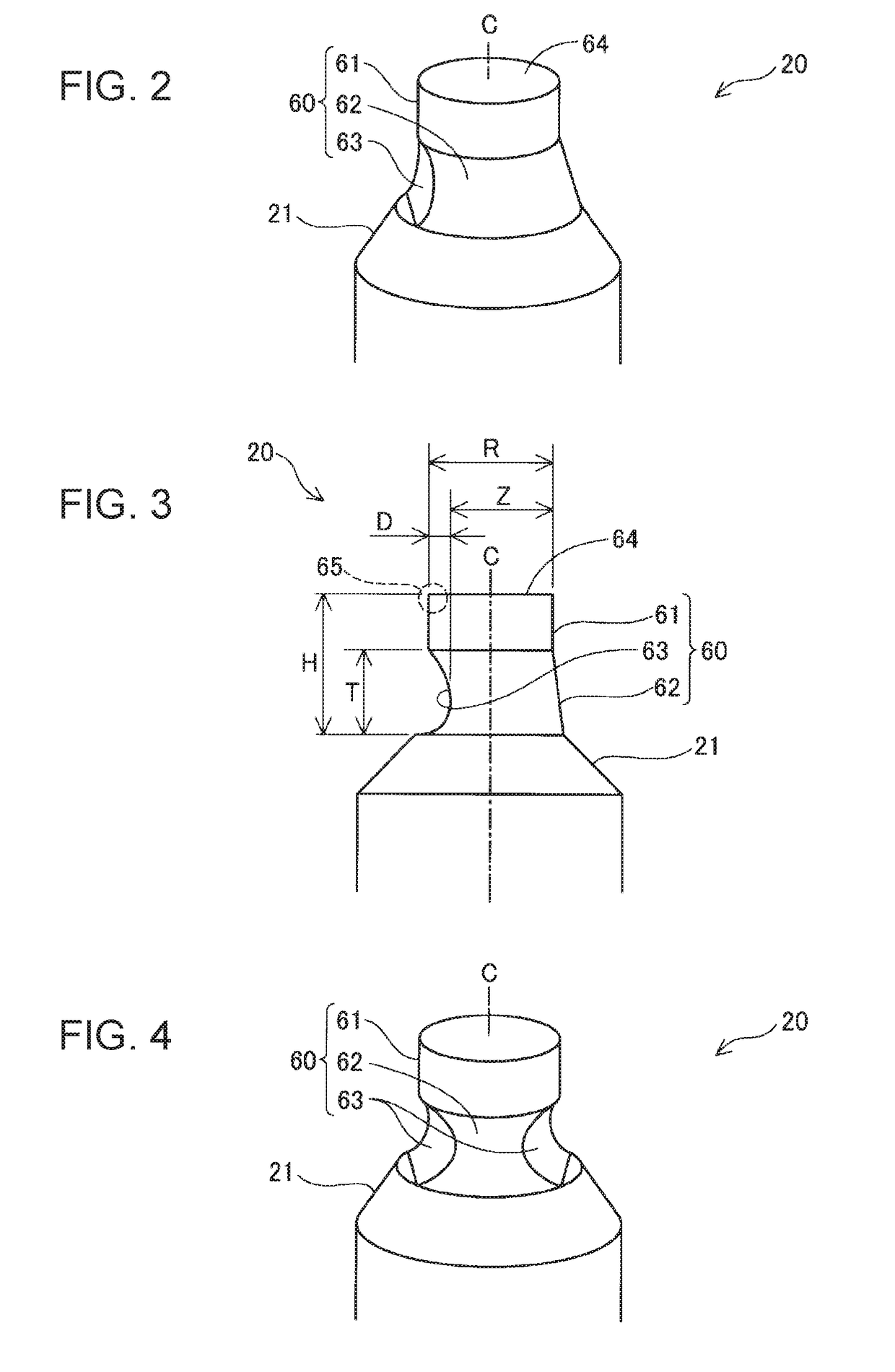
[0058]In the above-described embodiment, the projection 60 includes the noble metal tip 61 having a cylindrical shape. However, the shape of the noble metal tip 61 is not limited to a cylindrical shape. Furthermore, the noble metal tip 61 of the projection 60 may be omitted. In such a case, the projection 60 is composed of the electrode base material 21, and the recess 63 is formed in the side surface of the electrode base material 21.

second modification

[0059]In the above-described embodiment, the recess 63 is formed in the projection 60 during the laser welding process. However, the recess 63 may instead be formed by, for example, a cutting process using a drill or the like or a punching process.


PUM


Abstract

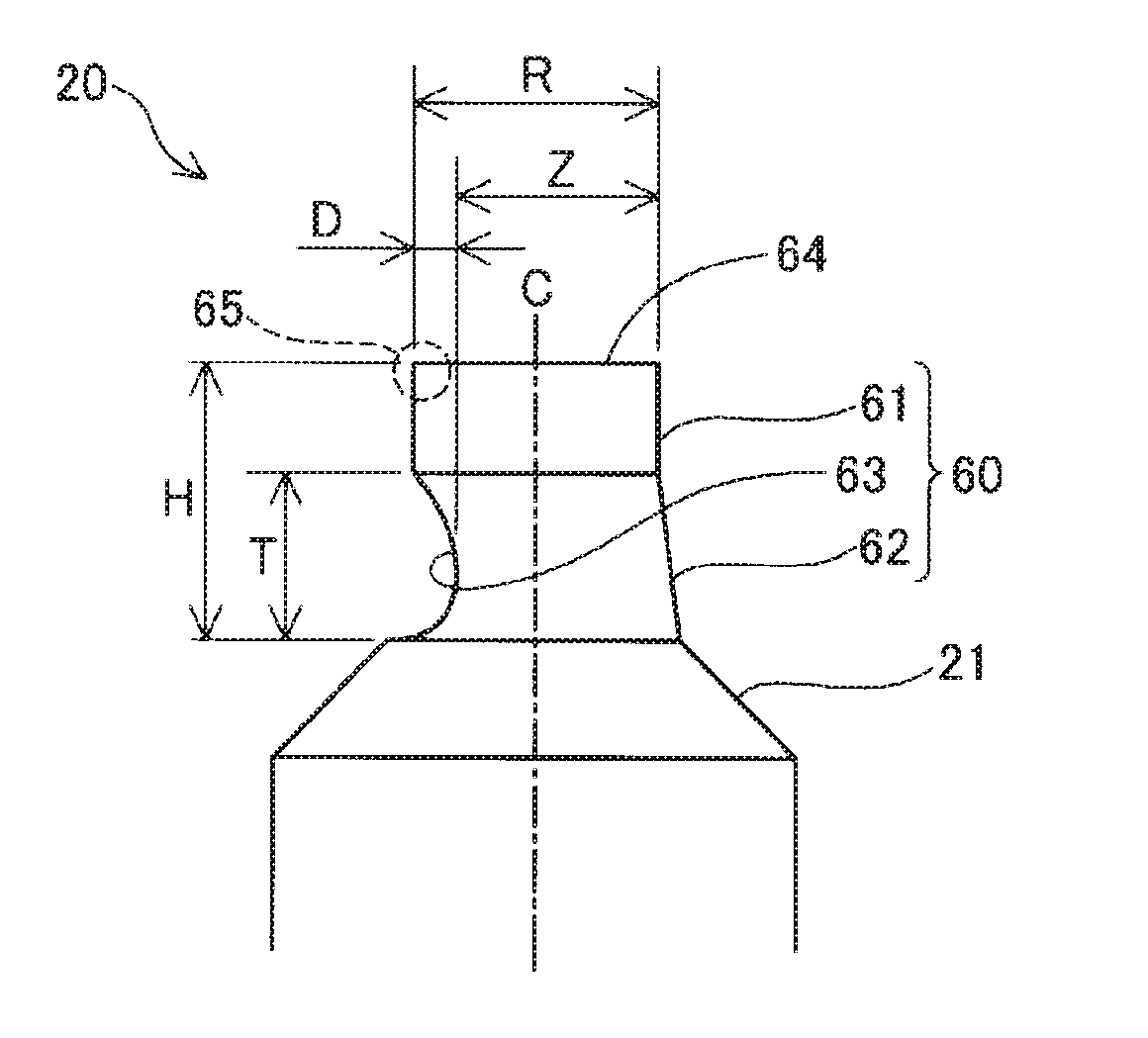
A spark plug includes a metal shell, an insulator, a center electrode, and a ground electrode. At least one of the center electrode and the ground electrode includes a projection having a columnar shape. The projection projects toward the other of the center electrode and the ground electrode and forms the discharge gap. A portion of a side surface of the projection has a recess. A melted portion is formed by melting the noble metal tip and an electrode base material. The recess is formed in the melted portion. When D is a depth of the recess from a side surface of the noble metal tip and R is a diameter of the noble metal tip, 0.05 mm≦D≦0.3×R is satisfied.

Description

RELATED APPLICATION[0001]This application claims the benefit of Japanese Patent Application No. 2015-116285, filed Jun. 9, 2015, and Japanese Patent Application No. 2016-065141, filed Mar. 29, 2016.FIELD OF THE INVENTION[0002]The present invention relates to a spark plug.BACKGROUND OF THE INVENTION[0003]The ignitability of spark plugs has been increased by, for example, increasing the ignition energy applied to the spark plug (see Japanese Unexamined Patent Application Publication No. 2013-108465).[0004]However, to increase the ignition energy, an ignition coil or the like capable of generating a large amount of energy is required, and therefore the cost of the entire ignition system is increased.[0005]Accordingly, a technology for increasing the ignitability of a spark plug with a simple structure is in demand.[0006]The present invention has been made to solve the above-described problem, and can be embodied in the following forms.SUMMARY OF THE INVENTION[0007](1) In accordance to ...

Claims


Application Information

Patent Timeline
Patent Type & Authority Patents(United States)
IPC IPC(8): H01T13/20H01J13/32H01T13/39H01T13/32H01T13/16
CPCH01T13/39H01T13/20H01T13/32H01T13/16
Inventor YAMAMURA, NAOFUMIISHII, KUNIYUKIONODA, NAOYAODO, HIROYUKI
Owner NGK SPARK PLUG CO LTD
Learn More