Porous tissue ingrowth structure

a technology of porous tissue and ingrowth structure, which is applied in the field of medical implants, can solve the problems of reducing the strength of the scaffold known in the art, reducing the cost of manufacturing of the implant formed from the laminate of thin metal layers, and reducing the thickness of the minimum strut. , to achieve the effect of reducing the minimum strut thickness, reducing the cost of manufacturing, and increasing the strength of the produced three-dimensional scaffold

Active Publication Date: 2017-08-08
SMED TATD
View PDF111 Cites 22 Cited by
  • Summary
  • Abstract
  • Description
  • Claims
  • Application Information

AI Technical Summary

Benefits of technology

[0012]An advantage of the present invention is that, due to the alignment of the pore patterns, the strength of the produced three-dimensional scaffold is increased, especially shear strength in planes parallel to individual layers.
[0013]Another advantage is provided by the present invention since the alignment of the pore patterns further requires the alignment of the struts surrounding the pores at the adjacent surfaces of adjacent layers, more cost effective manufacturing is possible through reduction of the minimum strut thickness required. Additionally, the configuration and positioning of the layers forming the 3-dimensional scaffold according to the present invention provide for improved aesthetics of the resulting scaffold.

Problems solved by technology

However, the scaffolds known in the art which are constructed to encourage bone ingrowth have reduced strength due to the low contact area between adjacent layers.
Accordingly, if the scaffold struts are too thin, the scaffold will not satisfy the necessary strength.
Additionally, implants formed from the laminate of thin metal layers are costly to produce, since the scaffold's strength must be bolstered by increased minimum thickness of the layers.

Method used


Image

  • Porous tissue ingrowth structure
  • Porous tissue ingrowth structure
  • Porous tissue ingrowth structure

Examples


Embodiment Construction

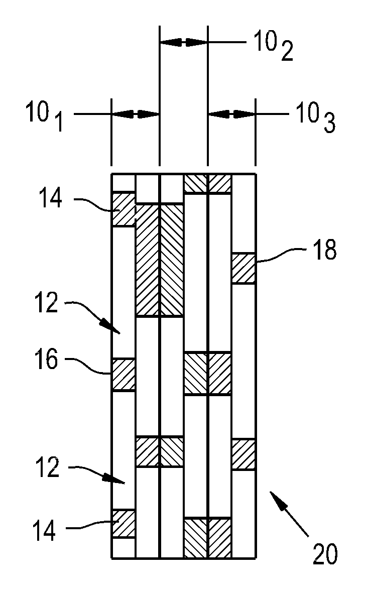
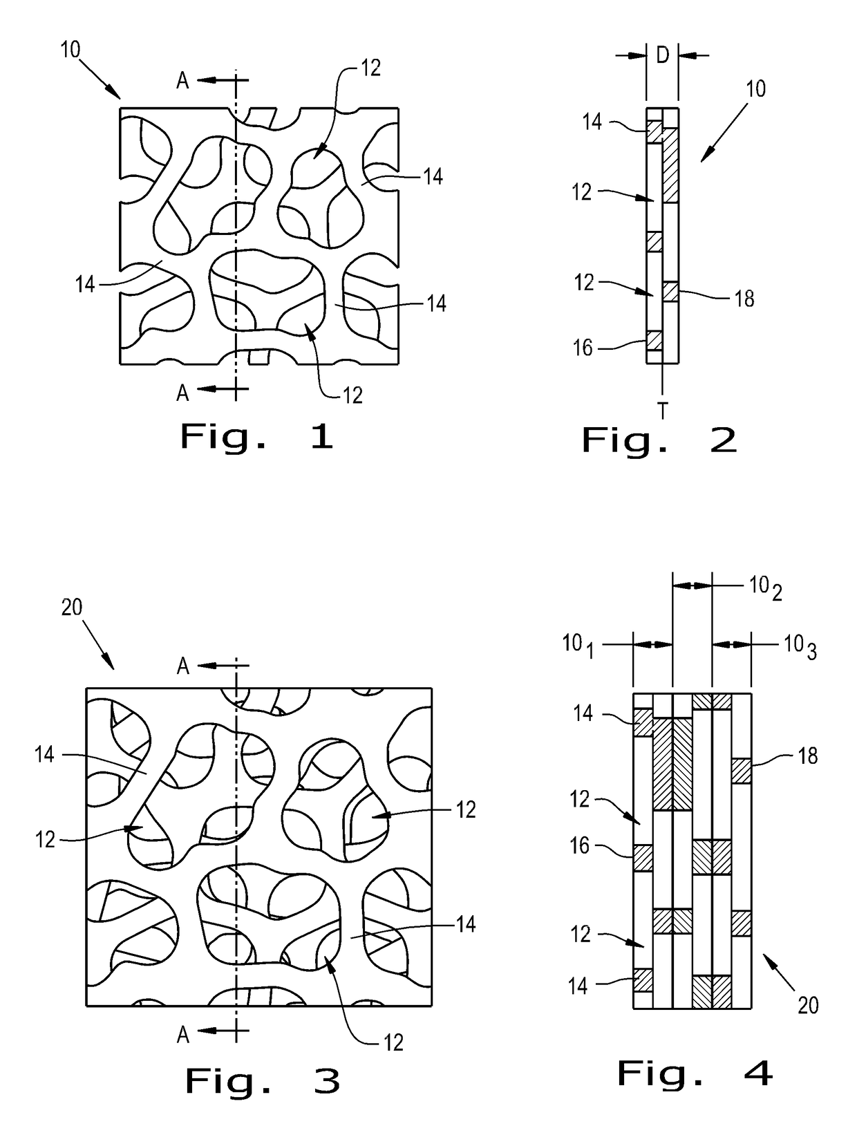
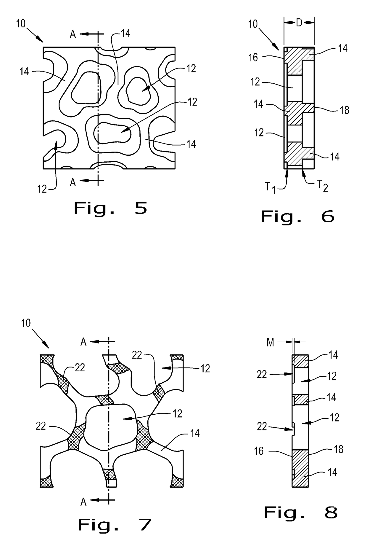
[0031]Referring now to the drawings, and more particularly to FIGS. 1 and 2, there is shown a single layer 10 of a three-dimensional scaffold for a medical implant according to the present invention. Single layer 10 includes a plurality of pores or through-holes 12 defined by a plurality of struts 14. The geometries of the pores 12 vary through a thickness D of each layer 10. Any layer thickness D can be used, for example layer thickness D may be in a range of, for example, between approximately 0.0001 inch (in) and 10 in, for example 0.0001 to 0.040 in, or 0.020 to 0.040 in. Further, struts 14 are defined as bars of material extending between and defining pores 12. Each layer 10 has a first pore pattern at a top surface 16 and different, second pore pattern at an opposing, bottom surface 18. Transition from the first pore pattern to the second pore pattern takes place at a location or transition point T, where T is defined by the equation T=A*D, with T being a defined distance from...


PUM


Abstract

A three-dimensional scaffold for a medical implant includes a plurality of layers bonded to each other. Each layer has a top surface and a bottom surface and a plurality of pores extending from the top surface to the bottom surface. Each layer has a first pore pattern of the pores at the top surface and a different, second pore pattern at the bottom surface. Adjacent surfaces of at least three adjacent layers have a substantially identical pore pattern aligning to interconnect the pores of the at least three adjacent layers to form a continuous porosity through the at least three adjacent said layers.

Description

CROSS REFERENCE TO RELATED APPLICATIONS[0001]This is a non-provisional application based upon U.S. Provisional Patent Application Ser. No. 61 / 789,723, entitled “POROUS TISSUE INGROWTH STRUCTURE”, filed Mar. 15, 2013, which is incorporated herein by reference.BACKGROUND OF THE INVENTION[0002]1. Field of the Invention[0003]The present invention relates to medical implants, and, more particularly, to medical implants having a bone and tissue ingrowth structure, and to a method of manufacturing the medical implants.[0004]2. Description of the Related Art[0005]Implant fixation via bone and tissue integration into a porous scaffold has been in development since the 1950s, when polyvinyl sponges were implanted into canines (Bryan, R. S., et al., “The Effect of Polyvinyl-Formal (Ivalon) Sponge on Cortical Bone Healing.”Proceedings of the Staff Meetings, Mayo Clinic, 33 (1958): 453-457). The early 1970s saw the development of sintered beads and titanium fiber metal, which are still in use in...

Claims


Application Information

Patent Timeline
Patent Type & Authority Patents(United States)
IPC IPC(8): A61F2/44A61F2/30
CPCA61F2/44A61F2/442A61F2/4455A61F2002/30011A61F2002/30013A61F2002/30014A61F2002/3079A61F2002/3092A61F2002/30784A61F2002/30807A61F2002/30813A61F2002/30841A61F2002/30915A61F2002/30971Y10T156/10
Inventor NEBOSKY, PAUL S.STALCUP, GREGORY C.KNAPP, TROY D.
Owner SMED TATD
Why Eureka
Try Eureka