
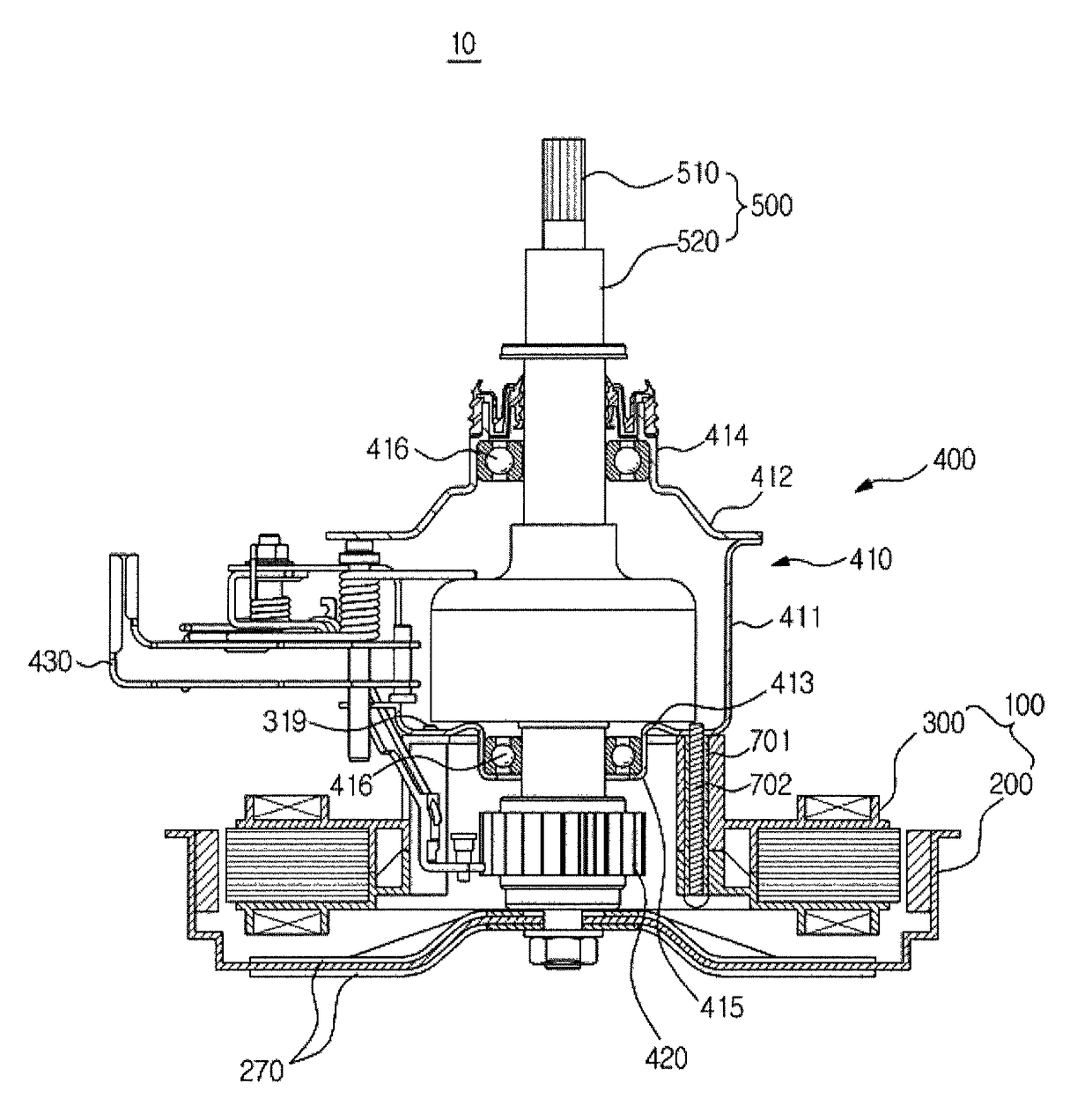
Driving apparatus for washing machine and washing machine having the same

a technology of driving apparatus and washing machine, which is applied in the field of washing machines, can solve problems such as difficulty in implementing the center of gravity, and achieve the effect of minimizing the coupling structure of a clutch and a motor

Active Publication Date: 2017-08-08
SAMSUNG ELECTRONICS CO LTD
View PDF17 Cites 2 Cited by
  • Summary
  • Abstract
  • Description
  • Claims
  • Application Information

AI Technical Summary

Benefits of technology

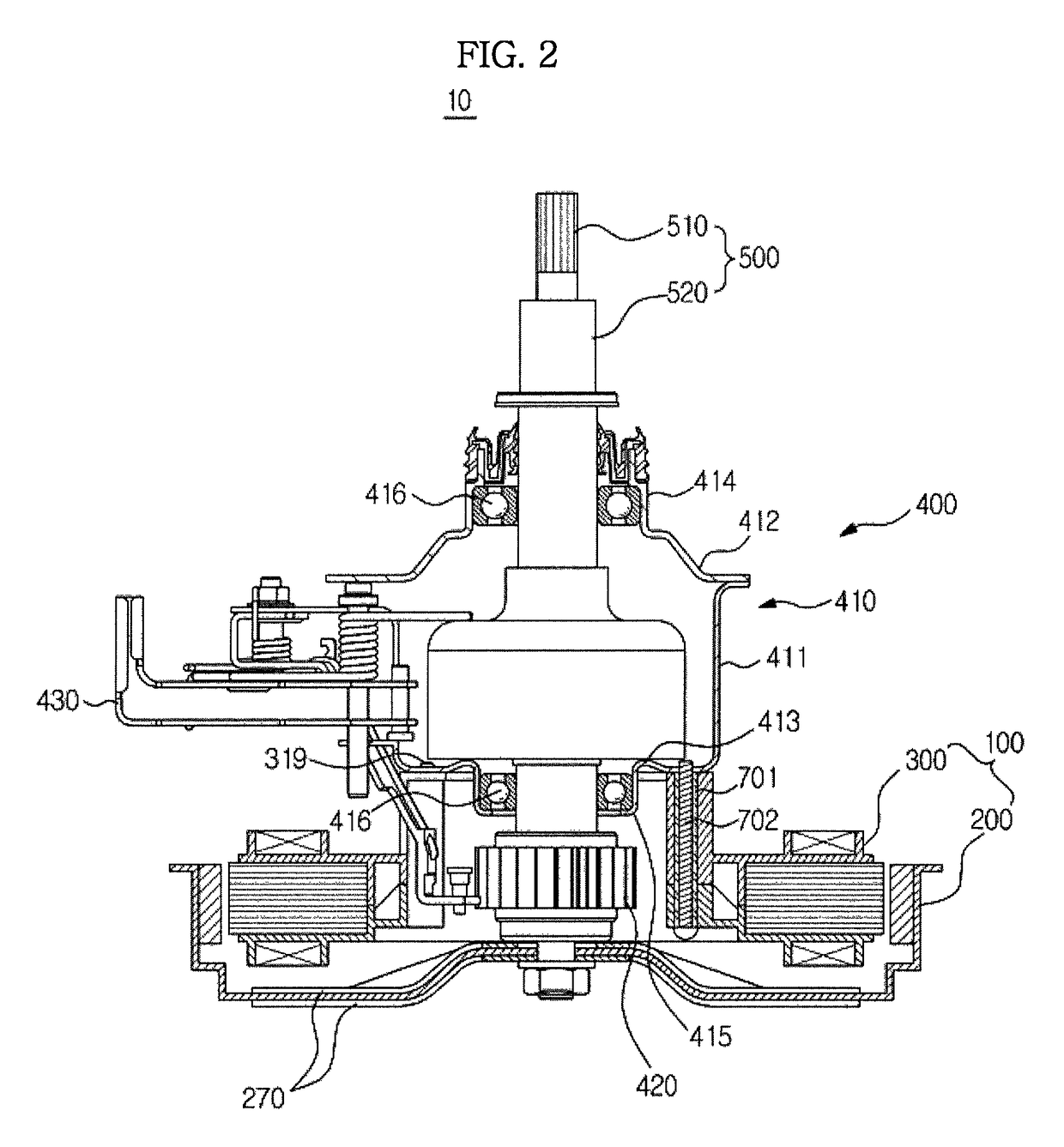
[0009]Therefore, it is an aspect of the present disclosure to provide a washing machine driving apparatus and a washing machine having the same, capable of minimizing the coupling structure of a clutch and a motor.
[0010]It is another aspect to provide a washing machine driving apparatus and a washing machine having the same, in which a stator divided into many parts is used and thus the productivity in manufacturing the stator is improved.
[0011]It is another aspect to provide a washing machine driving apparatus and a washing machine having the same, capable of preventing moisture from infiltrating into a hall sensor assembly.
[0025]The upper insulator is provided at the upper surface thereof with a connection part to which the hall sensor assembly is connected, and wherein the hall sensor assembly completely covers the connection part to prevent moisture from being infiltrated to the connection part.
[0032]Since a stator includes a stator core, an upper insulator and a lower insulator, the assembly of the stator is simplified and thus the cost required for assembling the stator is reduced.

Problems solved by technology

However, such a configuration has a difficulty in implementing the center of gravity.

Method used


Image

  • Driving apparatus for washing machine and washing machine having the same
  • Driving apparatus for washing machine and washing machine having the same
  • Driving apparatus for washing machine and washing machine having the same

Examples


Embodiment Construction

[0041]Reference will now be made in detail to the embodiments of the present disclosure, examples of which are illustrated in the accompanying drawings, wherein like reference numerals refer to like elements throughout.

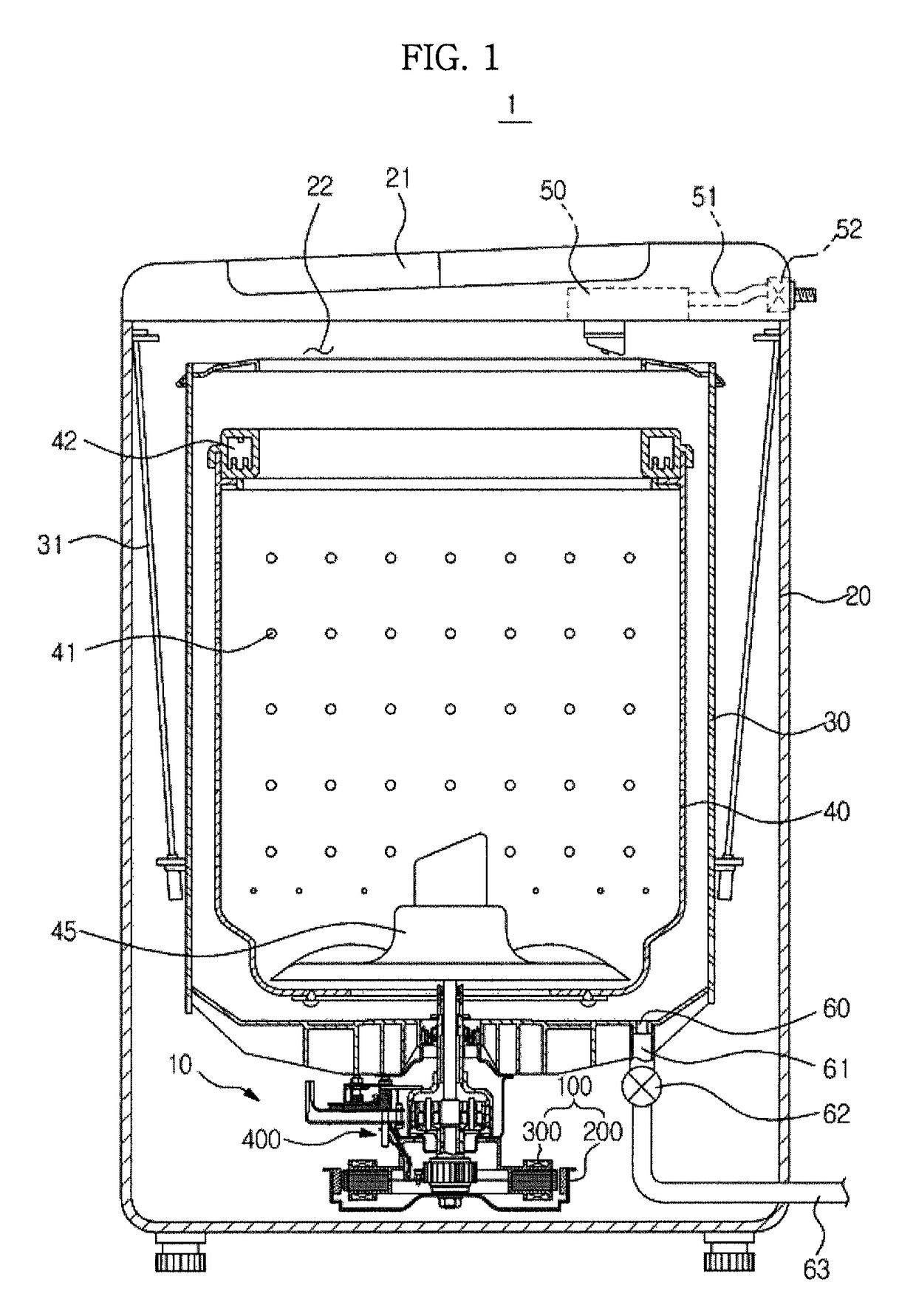
[0042]FIG. 1 is a cross-sectional view illustrating a washing machine according to an embodiment of the present disclosure.

[0043]Referring to FIG. 1, a washing machine 1 includes a cabinet 20 forming an external appearance of the washing machine 1; a tub 30 disposed inside the cabinet 20 to accommodate a washing water; a rotating tub 40 rotatably disposed inside the tub 30; and a pulsator 45 disposed inside the tub 40 to generate a stream of water.

[0044]An insert opening 22 is formed at an upper portion of the cabinet 20 such that laundry is inserted to the inside the rotating tub 40. The insert opening 22 is open and closed by a door 21 installed at the upper portion of the cabinet 20.

[0045]The tub 30 is hung on the cabinet 20 while being supported by a suspension ap...


PUM


Abstract

A washing machine driving apparatus and a washing machine having the same, capable of minimizing the coupling structure of a clutch and a motor and including a stator provided in a shape of a ring, a rotor disposed around the stator and rotating by electromagnetic interaction with the stator, and a clutch configured to transmit a rotary force of the rotor selectively to the rotating tub and the pulsator, wherein the stator comprises a stator core, an upper insulator covering an upper portion of the stator core and a lower insulator covering a lower portion of the stator core, and wherein the upper insulator has a mounting part protruding upward from an upper side of the upper insulator such that the clutch is coupled to the upper insulator.

Description

CROSS-REFERENCE TO RELATED APPLICATIONS[0001]This application claims priority to Korean Patent Applications No. 10-2011-0080586, filed on Aug. 12, 2011 in the Korean Intellectual Property Office, the disclosure of which is incorporated herein by reference.BACKGROUND[0002]1. Field[0003]Embodiments of the present disclosure relate to a washing machine, and more particularly, to a driving apparatus for selectively rotating a rotating tub and a pulsator in a washing machine.[0004]2. Description of the Related Art[0005]A washing machine is a machine configured to wash laundry by use of electric power, in general, includes a tub to accommodate a washing water; a rotating tub rotatably installed inside the tub; a pulsator rotatably installed at the bottom of the rotating tub; and a motor and a clutch that are configured to rotate the rotating tub and the pulsator.[0006]As the rotating tub and the pulsator rotate in a state that laundry and washing water are input in the rotating tub, the p...

Claims


Application Information

Patent Timeline
Patent Type & Authority Patents(United States)
IPC IPC(8): D06F23/00D06F37/40D06F37/30D06F23/04D06F37/20
CPCD06F37/40D06F23/04D06F37/206D06F37/304D06F37/12H02K11/215H02K7/10
Inventor CHOI, MYUNG GUILEE, WOON YONG
Owner SAMSUNG ELECTRONICS CO LTD
Learn More