Piping inspection robot and method of inspecting piping

a technology of piping inspection and inspection robot, which is applied in the direction of fluid tightness measurement, instruments, manufacturing tools, etc., can solve the problems of inability to find the occurrence position of corrosion and damage on the outer surface of the pipe body, the existence or non-existence of fluid leakage, and the thinning of the pipe wall, so as to improve mobility and operability, simplify the device configuration, and reduce the effect of weigh

Active Publication Date: 2017-08-08
MOBILE ROBOT RES
View PDF31 Cites 14 Cited by
  • Summary
  • Abstract
  • Description
  • Claims
  • Application Information

AI Technical Summary

Benefits of technology

[0033]The piping inspection robot of the present invention has a configuration in which a frame including a semicircular recessed portion is included, and a measuring device can be revolved around the piping in a state where a main body with a lower portion open is placed on an upper portion of the piping, whereby the device configuration can be simplified and the entire device can be decreased in weight, and the mobility and the operability can be improved. Since the lower portion is open, the robot can pass through a portion where the T-shaped stand that supports the lower portion of the piping exists.

Problems solved by technology

However, in the methods to perform an inspection from the inside of the pipe body, it is difficult to find occurrence positions of corrosion and damage occurring on the outer surface of the pipe body, and of pipe wall thinning, holes, and cracks due to the corrosion and damage, and the existence or non-existence of fluid leakage.
Especially, it is difficult to directly visually observe and find the abnormality that occurs on the pipe body covered with the lagging material and the like.
Further, the worker may not be able to come close to the piping in order to avoid risk of radiation exposure, and a work time in the vicinity of the piping may be restricted, in a piping facility of a nuclear power station and the like.
However, the method to access and inspect the piping from the ground may be restricted due to arrangement of other structural objects in the vicinity of the piping to be inspected or risk of the work environment, and the like, and in this case, the techniques disclosed in Patent Literatures 4 and 5 cannot handle the inspection.
Therefore, it is necessary to individually inspect the piping by dividing a predetermined length range into the upper half and the lower half, and thus workability of the inspection and inspection efficiency are low.
Therefore, it is necessary to configure configuration parts such as a traveling device in a complicated and strong manner, and the heavy load at the piping side becomes large and an operation needs time.

Method used


Image

  • Piping inspection robot and method of inspecting piping
  • Piping inspection robot and method of inspecting piping
  • Piping inspection robot and method of inspecting piping

Examples


Embodiment Construction

[0048]Hereinafter, a piping inspection robot according to an embodiment of the present invention will be described in detail with reference to the appended drawings.

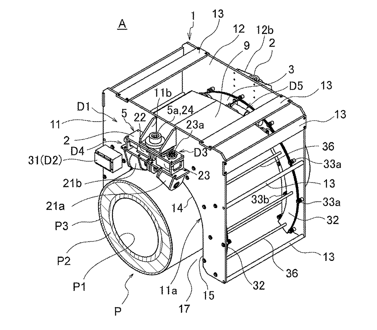
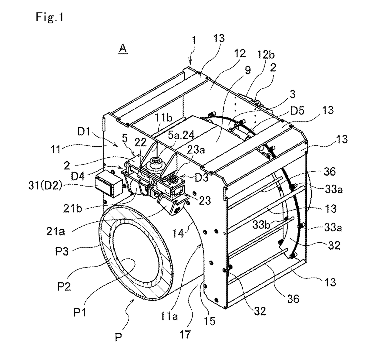
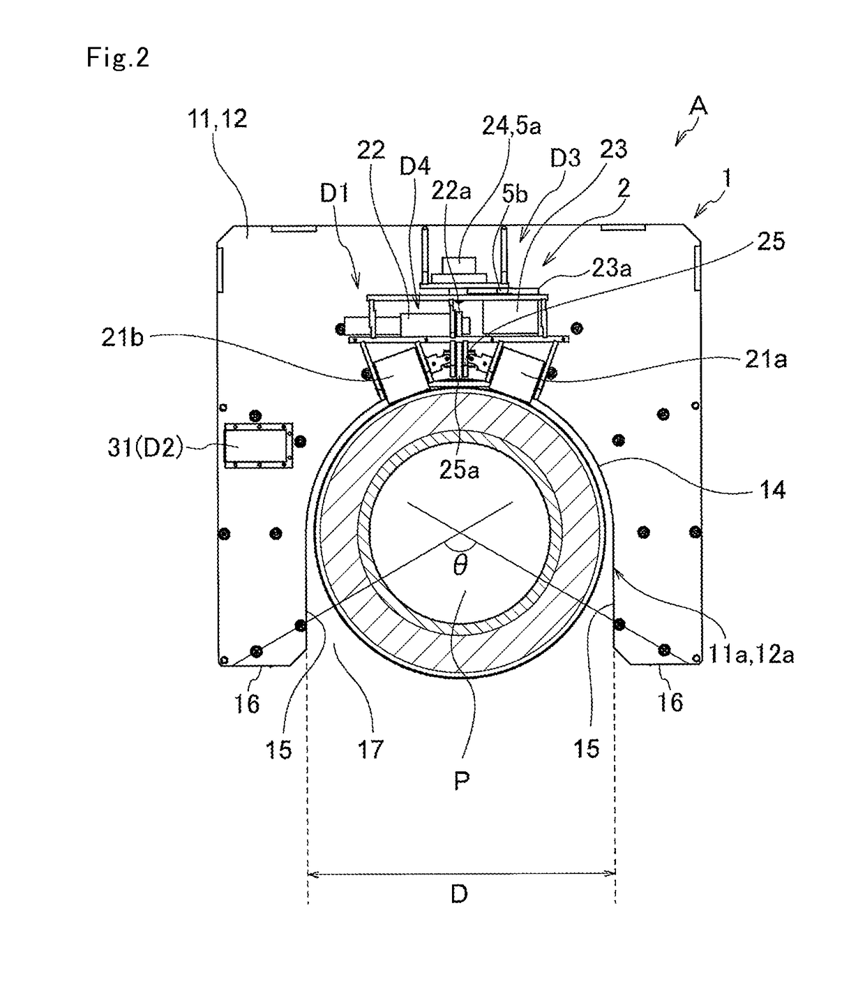
[0049]FIG. 1 is a perspective view of a piping inspection robot according to an embodiment of the present invention mounted on piping, FIG. 2 is a front view of the piping inspection robot,

[0050]FIG. 3 is a plan view of the piping inspection robot, FIG. 4 is a side view of the piping inspection robot, FIG. 5 is a vertical cross-sectional view of the piping inspection robot, FIG. 6 is a cross-sectional view of a principal part of the piping inspection robot, FIG. 7 is a vertical cross-sectional view of a central position of the piping inspection robot, FIG. 8 is a perspective view of the piping inspection robot in a state where a moisture measuring device (inspection device) is in a lower position, FIG. 9 is a perspective view illustrating a traveling device of the piping inspection robot, FIG. 10 is a perspective view il...


PUM

PropertyMeasurementUnit
θaaaaaaaaaa
angleaaaaaaaaaa
distanceaaaaaaaaaa

Abstract

Provided is an inspection robot that is self-propelled on piping, measures moisture contained in a lagging material using a mounted inspection device, for example, a neutron moisture meter, and detects risk of corrosion. The inspection robot includes a main frame 1 including a recessed part 17 fit onto an outer circumferential surface of piping P, a main frame drive mechanism (first drive mechanism) D1 that causes the main frame to advance / retract in an axis direction of the piping, a revolving member 32 supported in an advanceable / retractable manner along an arc-shaped locus in the recessed part of the main frame, a revolving member drive mechanism (second drive mechanism) D2 that moves the revolving member, and an inspection device mounted on the revolving member.

Description

RELATED APPLICATIONS[0001]This application is the U.S. National Phase of and claims priority to International Patent Application No. PCT / JP2013 / 083725, International Filing Date Dec. 17, 2013, entitled Pipe Inspection Robot, And Method For Inspection Of Pipe, which claims benefit of Japanese Patent Application No. JP2012-276238, filed Dec. 18, 2012, both of which are incorporated herein by reference in their entireties.TECHNICAL FIELD[0002]The present invention relates to a self-propelled piping inspection robot that inspects existence or non-existence of damage of piping, and a method of inspecting piping.BACKGROUND ART[0003]Piping installed in various plants and used for transferring fluids such as a liquid, powder, and gas has a structure in which an outer surface of a steel-made pipe body is covered with a heat insulating material (lagging material) and a protective iron sheet in order.[0004]As a technique to inspect abnormality of the pipe body such as damage, deterioration, an...

Claims


Application Information

Patent Timeline
Patent Type & Authority Patents(United States)
IPC IPC(8): G01M3/24F16L55/26G01N23/02G01N29/04G01N27/82G01M3/18G01M3/00B25J9/16F16L55/32G01N23/00F16L101/30
CPCG01M3/005B25J9/1679F16L55/26F16L55/32G01N23/00G01N23/005G01N23/025G01N27/82G01N29/04F16L2101/30G01N2223/613G01N2223/628G01N2291/269Y10S901/02Y10S901/19
Inventor KOYANAGI, EIJI
Owner MOBILE ROBOT RES
Why Eureka
Try Eureka