
Supply voltage generating circuit and switching power supply

a supply voltage and switching power supply technology, applied in the field of power electronics, can solve the problems of increasing manufacturing cost, complex structure of the transformer, and inability to provide the supply voltage of the control circuit, and achieve the effect of easy resonating in actual operation

Active Publication Date: 2017-08-08
SILERGY SEMICON TECH (HANGZHOU) CO LTD
View PDF30 Cites 2 Cited by
  • Summary
  • Abstract
  • Description
  • Claims
  • Application Information

AI Technical Summary

Benefits of technology

The solution provides improved controllability and stability for the control circuit, reduces circuit complexity, and prevents resonance, ensuring efficient energy transfer and stable operation of the switching power supply.

Problems solved by technology

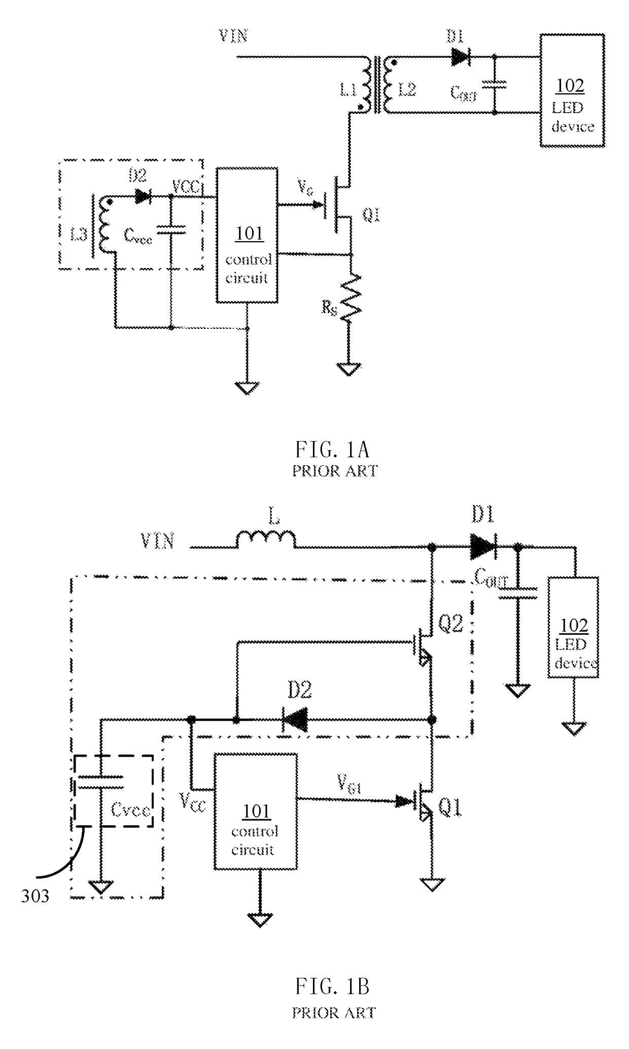
However, the transformer has a complex structure and increased manufacture cost because the auxiliary winding L3 must be included in the circuit.
However, the circuit scheme shown in FIG. 1B has the disadvantage that it may not be able to provide the supply voltage for the control circuit 101, because the second switch Q2 has a drain-source parasitic capacitance too small to ensure that the power capacitor CVCC is charged to a large voltage value when an input voltage VIN has a small value.
Moreover, the second switch Q2 has a source being grounded through the first switch Q1, and as a result, it cannot be turned off completely.
The circuit also has the problem of easily resonating in actual operation.

Method used


Image

  • Supply voltage generating circuit and switching power supply
  • Supply voltage generating circuit and switching power supply
  • Supply voltage generating circuit and switching power supply

Examples


Embodiment Construction

[0051]Those embodiments of the present disclosure will be described clearly and completely in connection with appended drawings. It is apparent that the embodiments described hereinbelow are only some but not all of the embodiments of the present disclosure. All of other embodiments, which are obtained by one skilled in the art from the embodiments described hereinbelow without the need for creative work, will fall within the scope of the present disclosure.

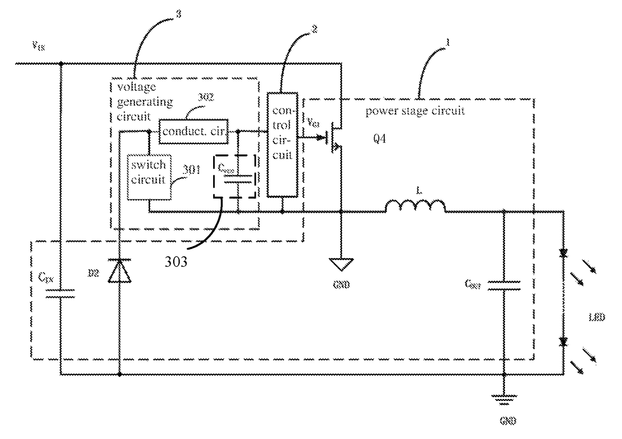
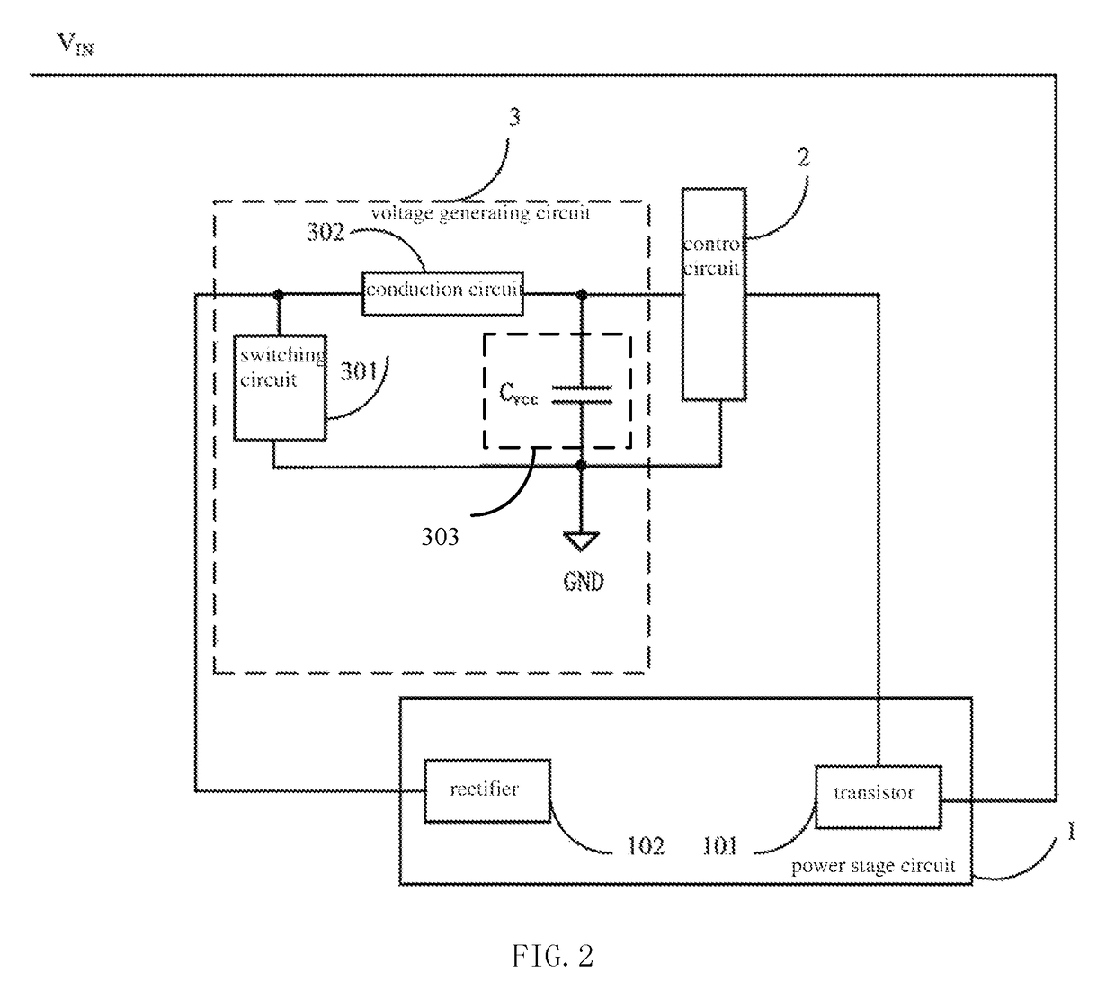
[0052]FIG. 2 is a schematic circuit diagram of a supply voltage generating circuit according to an embodiment of the present disclosure.

[0053]A supply voltage generating circuit provides a supply voltage to a power terminal of a control circuit 2 in a switching power supply which has a power stage circuit 1 including a main power transistor 101 and a rectifying device 102. The supply voltage generating circuit 3 includes a switching circuit 301, a unidirectional conduction circuit 302 and an energy storage circuit 303.

[0054]The s...


PUM


Abstract

The present disclosure relates to a supply voltage generating circuit and a switching power supply having the circuit. The supply voltage generating circuit provides a supply voltage for a power terminal of a control circuit in the switching power supply. The supply voltage generating circuit includes a switching circuit, a unidirectional conduction circuit and an energy storage circuit. In a time period during which a main power transistor is turned off, the switching circuit is turned off and a rectifying device provides a current to the energy storage circuit through the unidirectional conduction circuit, in a case that the supply voltage is smaller than a predetermined voltage reference; and the switching circuit is turned on and the current output from the rectifying device flows to the switching circuit, in a case that the supply voltage is larger than or equal to the predetermined voltage reference. When the supply voltage generating circuit is used in a switching power supply, the control circuit has improved controllability for supplying electric energy, and the switching power supply has an increased integration level and a simplified circuit structure, and will not be adversely influenced by resonance.

Description

CLAIM OF PRIORITY[0001]This application claims priority to Chinese Application No. 201410309928.8, filed Jul. 1 2014 (published as CN 104038031 A), which is hereby incorporated by reference.BACKGROUND OF THE INVENTION[0002]Field of the Invention[0003]The present disclosure relates to the field of power electronics, and more particularly, to a supply voltage generating circuit and a switching power supply.[0004]Description of the Related Art[0005]With rapid development in electronic information industry, switching power supplies are widely utilized in various fields, such as computers, electrical equipment, instrumentation, light-emitting diodes (LEDs), medical devices, military equipment and so on. A conventional switching power supply has a circuit structure including a power stage circuit and a control circuit and a supply voltage generating circuit which supplies electric energy to the control circuit.[0006]FIG. 1A and FIG. 1B are schematic diagrams showing a conventional switchi...

Claims


Application Information

Patent Timeline
Patent Type & Authority Patents(United States)
IPC IPC(8): H02M3/155H02M3/335H02M1/00
CPCH02M3/155H02M3/33523H02M2001/0006H02M1/0006
Inventor DENG, JIAN
Owner SILERGY SEMICON TECH (HANGZHOU) CO LTD
Learn More