Control device of coal pulverizer
a control device and coal pulverizer technology, which is applied in the direction of lighting and heating apparatus, combustion process, combustion regulation, etc., can solve the problems of disturbance of coal output from coal pulverizer, disturbance of steam temperature or steam pressure in the boiler, and inability to perform stable control, etc., to achieve the effect of stable response control
- Summary
- Abstract
- Description
- Claims
- Application Information
AI Technical Summary
Benefits of technology
Problems solved by technology
Method used
Image
Examples
first embodiment
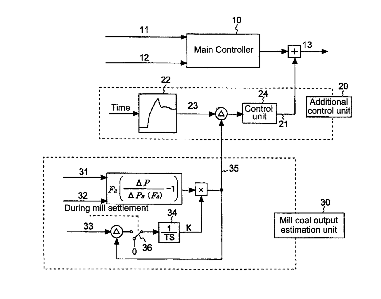
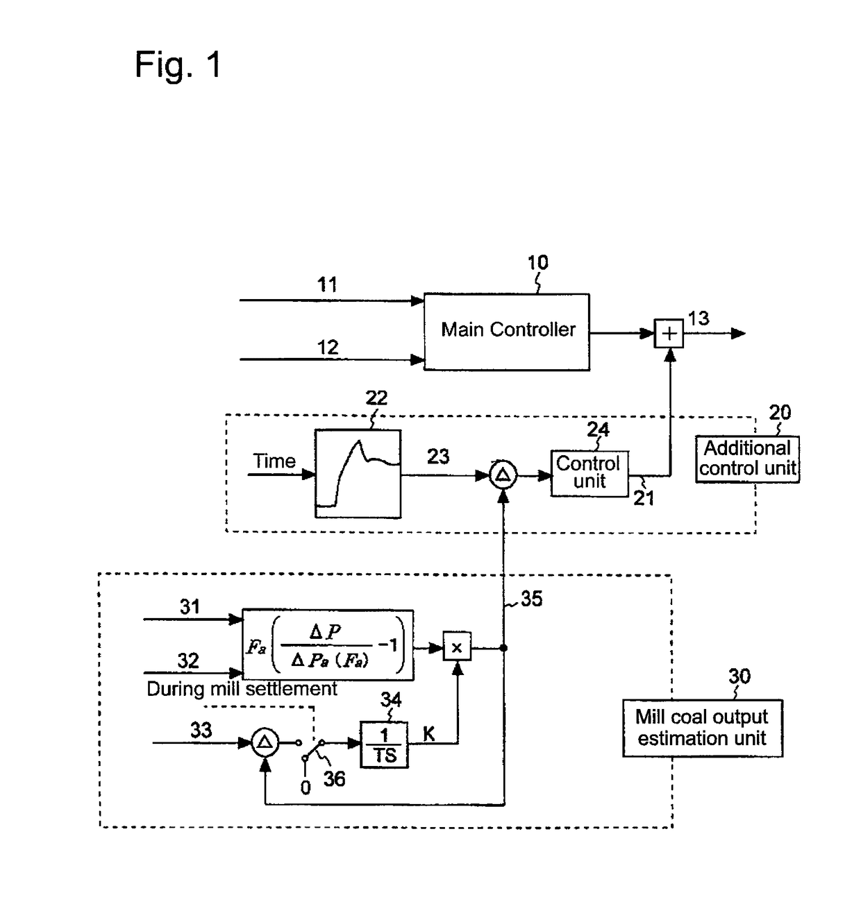
[0037]FIG. 1 is a block diagram illustrating the configuration of a control device according to a first embodiment of the invention. This invention is adapted to add an output signal of a control system using the deviation of a standard mill coal output pattern and a mill coal output pattern during current operation to a primitive signal of a conventional control system as a correction signal, thereby performing mill coal output control more stably, and the first embodiment is configured to use a coal feed rate command value as a command signal associated with a coal feed rate.
[0038]In FIG. 1, the control device of the first embodiment includes a main controller 10 that is a conventional control system, an additional control unit 20, and a mill coal output estimation unit 30.
[0039]The mill coal output estimation unit 30 measures a mill furnace differential pressure (ΔP) 31 and an air flow rate (Fa) 32 that are existing detecting elements, and estimates a mill coal output. The mill f...
second embodiment
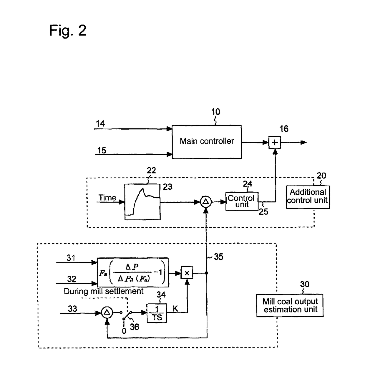
[0050]FIG. 2 is a block diagram illustrating the configuration of a control device according to a second embodiment of the invention.
[0051]The second embodiment is configured to use the MRS rotation frequency of the coal pulverizer as a command signal associated with the coal feed rate.
[0052]In FIG. 2, the control device of the second embodiment includes a main controller 10 that is a conventional control system, an additional control unit 20, and a mill coal output estimation unit 30.
[0053]The mill coal output estimation unit 30 and the additional control unit 20 are the same as those of the first embodiment.
[0054]A mill coal feed rate command 14 and a mill current 15 are input to the main controller 10, and arithmetic processing is performed on the basis of the input, thereby obtaining an MRS rotation frequency command value 16. At this time, an MRS rotation frequency command correction value 25 obtained by the mill coal output estimation unit 30 and the additional control unit 20...
third embodiment
[0056]FIG. 3 is a block diagram illustrating the configuration of a control device according to a third embodiment of the invention.
[0057]The third embodiment is configured to use the load pressure of an oil pressure load device provided in the coal pulverizer as a command signal associated with the coal feed rate. The load pressure represents a pressure applied to the rollers in the coal pulverizer.
[0058]In FIG. 3, the control device of the third embodiment includes a main controller 10 that is a conventional control system, an additional control unit 20, and a mill coal output estimation unit 30.
[0059]The mill coal output estimation unit 30 and the additional control unit 20 are the same as those of the first embodiment.
[0060]A mill coal feed rate command 17 and a roll lift 18 are input to the main controller 10, and arithmetic processing is performed on the basis of the input, thereby obtaining an oil pressure load device pressure setting value 19. At this time, an oil pressure l...
PUM
 Abstract
Description
Claims
Application Information
 - R&D
- Intellectual Property
- Life Sciences
- Materials
- Tech Scout
- Unparalleled Data Quality
- Higher Quality Content
- 60% Fewer Hallucinations
Browse by: Latest US Patents, China's latest patents, Technical Efficacy Thesaurus, Application Domain, Technology Topic, Popular Technical Reports.
© 2025 PatSnap. All rights reserved.Legal|Privacy policy|Modern Slavery Act Transparency Statement|Sitemap|About US| Contact US: help@patsnap.com


