Thermal management system for the feeding of fuel in internal combustion engines

a technology of management system and internal combustion engine, which is applied in the direction of mechanical equipment, fuel injection apparatus, and thermal treatment of fuel, etc., can solve the problems of high pollution level, discharge of vehicle battery after a few successive starts, and damage to the environment, so as to reduce fuel consumption and improve engine efficiency , the effect of reducing damag

Active Publication Date: 2017-09-05
MAHLE METAL LEVE
View PDF20 Cites 5 Cited by
  • Summary
  • Abstract
  • Description
  • Claims
  • Application Information

AI Technical Summary

Benefits of technology

[0031]The system proposed herein and defined above allows the fuel, whether single or in a mixture, to be conducted to the injection system of the engine in an improved temperature condition for its combustion and being automatically controlled.
[0032]The present system allows the fuel to be fed to the engine at suitable temperature and pressure values, thereby reducing fuel consumption, reducing damages to the environment and improving the efficiency both of the engine and of the vehicle to which it is associated, the thermal energy used for the selective heating of the fuel being obtained from the thermal energy dissipated by the internal combustion engine.

Problems solved by technology

There are well known in the art the cold start problems in the internal combustion engine of a vehicle in days in which the temperature is lower than 18 degrees Celsius, when the engine is supplied with a fuel mixture containing more than 85% ethanol and less than 15% gasoline.
The ethanol and the methanol, for example, present a high flash point and, for such reason, these fuels or mixtures containing a substantial percentage of these fuels, when below a certain temperature, do not spray adequately, impairing or even preventing its explosion inside the combustion chamber.
However, the technique of injecting gasoline during the engine start causes a high level of emission of pollutants.
A major challenge of using the preheating system is due to the need for developing highly efficient heaters, otherwise the high electrical energy demanded by the cold start heaters may cause the discharge of the vehicle battery after a few successive starts.
Thus, the technical solutions presented so far only target the solution of the “cold start problem”.
However, the “cold start problem” is just one of the many problems regarding efficiency and emission of pollutants caused by the burning of the cold or not heated fuel.
Besides the cold start problems in low temperature environments when using a fuel of high flash point, there is an additional problem, caused by the natural difficulty of burning any fuel, when the latter is at a temperature interiorly distant from that of its flash point, or commonly named “cold fuel”.
However, this is not a working condition which presents an optimized thermo-energetic efficiency.
In “flex vehicles” (driven by ethanol and / or gasoline in any mixture proportion) it is known that the engine yield is not optimized, since it is an engine which has to function reasonably well with both types of fuel, however it is not the ideal engine to run only on gasoline or only on ethanol.
Presently, the heat transmitted to the radiator water is lost, even unwanted energy, since if this heat is stored in the water the latter loses its efficiency as a thermal exchange fluid.
The oil, when overheated, loses viscosity and is more exposed to deterioration, and therefore loses its lubrication properties, which may cause from poor operation of the engine components to major damages or even destruction of the vehicle engine.
However, oil coolers presently used do not exchange heat with the fuel.

Method used


Image

  • Thermal management system for the feeding of fuel in internal combustion engines
  • Thermal management system for the feeding of fuel in internal combustion engines
  • Thermal management system for the feeding of fuel in internal combustion engines

Examples


first embodiment

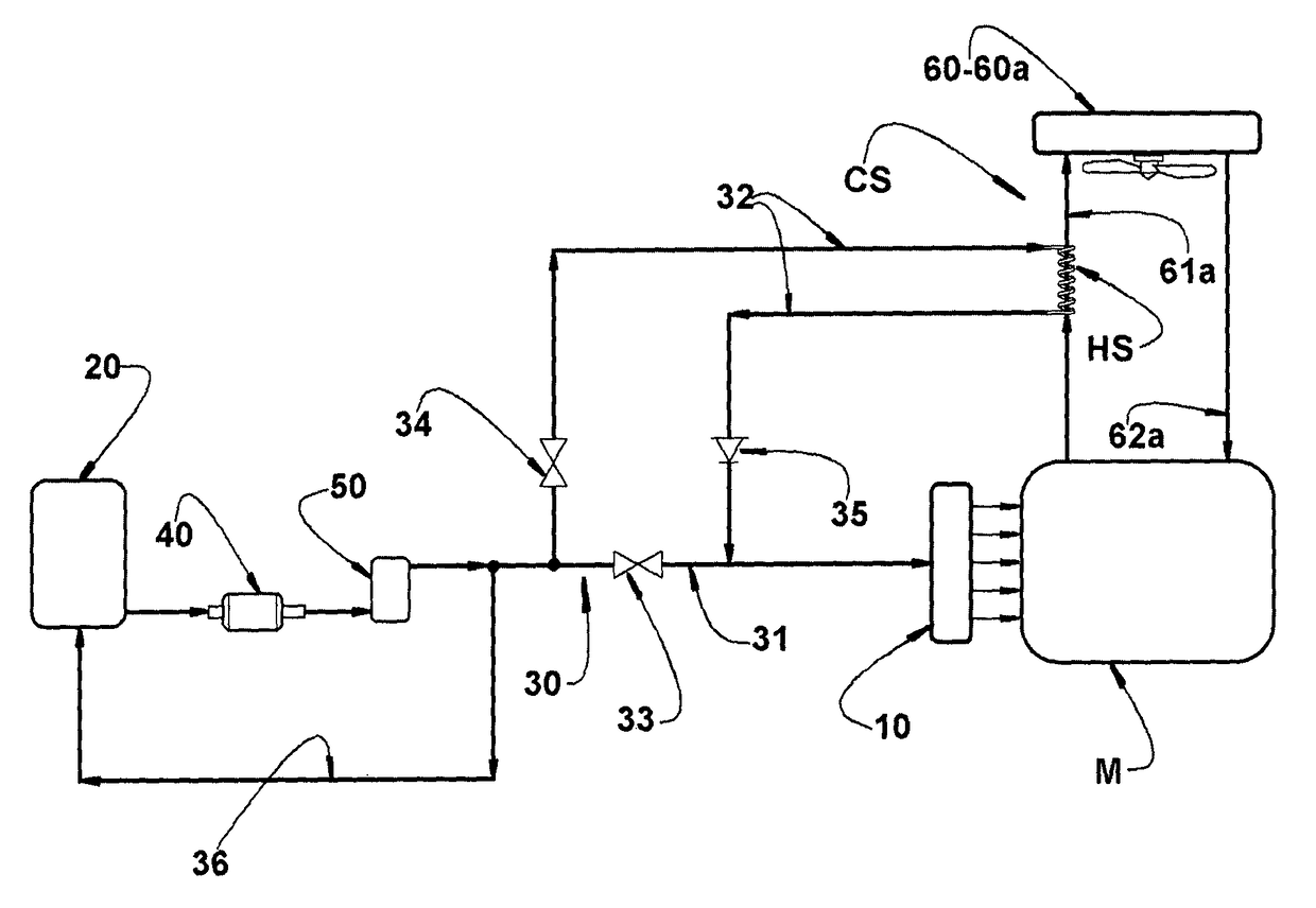
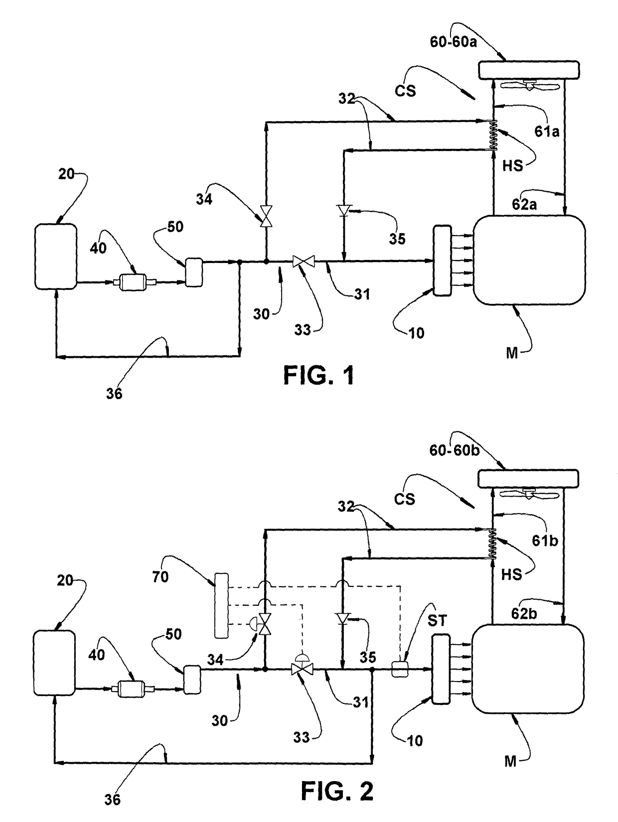
[0044]In said first embodiment, the fuel feed line 30 comprises a first segment 31, directly connected to the injection system 10 and provided with a first valve 33, and a second segment 32 which defines a by-pass to the first segment 31 and which is located in order to absorb thermal energy from a heat source HS defined by the hot fluid, in the form of hot cooling water, which is taken, through the hot fluid duct 61a, to the heat exchanger 60 defined by the radiator 60a.

[0045]The second segment 32 of the fuel feed line 30 is provided with a second valve 34, located upstream the heat source HS, and with a one-way valve 35 located downstream said heat source HS.

[0046]The thermal energy absorption from the heat source HS may be carried out in different ways, such as, for example, by winding an extension of the second segment 32 of the fuel feed line 30 around the hot fluid duct. 61a leading to the heat exchanger 60 which, in FIG. 1, is defined by the radiator 60a. This construction i...

second embodiment

[0052]In FIG. 2 of the attached drawings it is illustrated, a second embodiment for the present management system, when applied to an engine M presenting the same basic characteristics already described in relation to the engine represented in FIG. 1 and which are presented with the same reference numbers.

[0053]In said second embodiment, the engine M is provided with a cooling system CS which uses a heat exchanger 60, in the form of an oil radiator 60b, and a cooling fluid defined by the lubricant oil of the engine M and which circulates, by means of a hot fluid duct 61b and a cooled fluid duct 62b, through parts of the engine M and through the heat exchanger 60.

[0054]As already described above in relation to the construction of FIG. 1, in the construction of FIG. 2 the fuel feed line 30 comprises the same first and second segments 31, 32 located in the same manner and also provided with a first valve 33, a second valve 34 and a one-way valve 35, which operate according to the tempe...

third embodiment

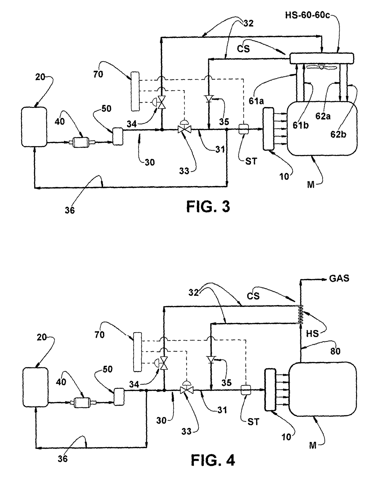
[0059]In FIG. 3 of the attached drawings is illustrated a third embodiment for the present management system, when applied to an engine M presenting the same basic characteristics already described in relation to the engine represented in FIGS. 1 and 2 and which are identified with the same reference numbers.

[0060]In said third embodiment, the engine M is provided with a cooling system CS which uses a heat exchanger 60, in the form of a double radiator, of water and oil, built to simultaneously receive a flow of the lubricant oil from the engine M, a flow of cooling fluid, usually water based, and also a flow of fuel to be supplied to the injection system 10 of the engine M.

[0061]In this third embodiment the cooling of the engine M is carried out by the circulation of water through the heat exchanger 60, through a hot fluid duct 61a and through a cooled fluid duct 62a, both ducts allowing the water to leave the engine M through the hot fluid duct 61a, through the double radiator 60c...


PUM


Abstract

The system is applied to an engine (M) having an injection system, a fuel feed line and a cooling system (CS), by means of a cooling fluid which circulates, through hot fluid ducts and cold fluid ducts, through the engine (M) and through a heat exchanger. The feed line has a first segment, connected to the injection system and provided with a first valve, to be closed when the fuel temperature is below a maximum value, and open when the fuel temperature reaches the maximum value. The feed line also has a second segment derived from the first and absorbing thermal energy from the hot fluid duct or from the combustion gases and provided with a second valve which remains open while the fuel temperature is lower than the maximum value, and which is closed when said temperature reaches the maximum value.

Description

CROSS REFERENCE TO RELATED APPLICATIONS[0001]The present application is the U.S. National Phase of International Patent Application Serial No. PCT / BR2014 / 000066, filed on Feb. 25, 2014, which claims priority to Brazilian Patent Application Serial No. 1020130043826, filed Feb. 25, 2013. The contents of the foregoing applications are hereby incorporated by reference in their entireties.FIELD OF THE INVENTION[0002]The present invention refers to a system for allowing the controlled heating of the fuel to be injected in an internal combustion engine of the type which may run on more than one fuel, each presenting a respective flash or vaporization point different than those of the other fuels.[0003]The thermal management system of the fuel to be supplied to the engine, which is the object of the present invention, was developed to operate only after the engine starts or during and also after the engine start, during the normal operation of the latter.BACKGROUND OF THE INVENTION[0004]The...

Claims


Application Information

Patent Timeline
Patent Type & Authority Patents(United States)
IPC IPC(8): F02M31/00F02M31/14F02D19/06F02D19/08F02M43/04
CPCF02D19/0605F02D19/08F02D19/084F02M31/14F02M43/04Y02T10/126Y02T10/36Y02T10/12Y02T10/30
Inventor AMARAL, TADEU MIGUEL MALAGOBUENO, RICARDO ROVERIYOSHINO, FERNANDO JUN
Owner MAHLE METAL LEVE
Why Eureka
Try Eureka