Autonomous aerial cable inspection system

Active Publication Date: 2017-09-05
GOOGLE LLC
View PDF11 Cites 55 Cited by
  • Summary
  • Abstract
  • Description
  • Claims
  • Application Information

AI Technical Summary

Benefits of technology

[0003]One aspect of the disclosure provides aerial inspection apparatus, including an aerial vehicle, an articulated arm coupled to the aerial vehicle at a first end, and an end effector coupled to a second end of the articulated arm, the end effector sized and shaped to extend at least partially around an aerial cable, with one or more sensors positioned along an inner surface of the end effector. Further, a control unit in the apparatus is configured to receive information from the one or more sensors, and to adjust at least one of a position of the aerial vehicle, movement of the articulated arm, or movement of the end effector in response to information detected by the one or more sensors so as to maintain a predetermined relative position of the end effector with respect to the cable. The end effector may include a base plate, a first tong extending from an upper portion of the base plate, and a second tong extending from a lower portion of the base plate, wherein the one or more sensors and/or cameras are located along a length of each tong and the base plate. The cameras are adapted to capture a 360 view of the aerial cable. The control unit is configured to automatically maintain a non-contacting position of the one or more sensors in relation to the aerial cable.
[0004]Another aspect of the disclosure provides a system including o

Problems solved by technology

Aerial cables, such as fiber cables, can become damaged by squirrel chew, fireworks, gun shots, weather, wear, etc.
Current methods of inspecting aerial fiber cable lines over long distances for sheath integrity or damage are slow, cumbersome and sometimes introduce unsafe practices or methods.
As it is typically very difficult to locate where the cable is damaged and then repair it, service interruptions

Method used


Image

  • Autonomous aerial cable inspection system
  • Autonomous aerial cable inspection system
  • Autonomous aerial cable inspection system

Examples


examples implementations

[0082

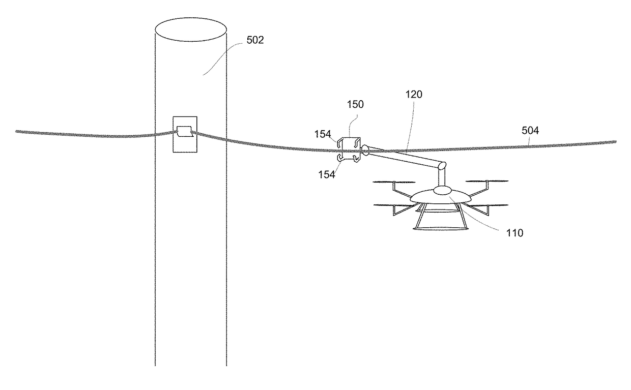
[0083]The subject matter described herein may be used in any of a number of different situations. As one example, the aerial inspection system described above may be used in responding to outside plant (OSP) network (Layer 1) service disrupting events. With assistance from proprietary network outage monitoring systems and network infrastructure geographic information systems (GIS), the apparatus may be rapidly dispatched from a secure base facility to the affected area. The autonomous cable inspection system enables the operations center personnel to quickly assess the situation, identify the level of network damage, and dispatch the appropriate resources. The aerial inspection system may be programmed to automatically return to the base facility for maintenance and charging in response to predetermined events, such as a detection of a low battery level, a need for repairs, or completion of a specified job.

[0084]With a direct flight path to the outage area, the UAV can arrive o...


PUM


Abstract

An aerial inspection system is provided, including an unmanned aerial vehicle (UAV) having an articulated arm coupled thereto. An end effector is coupled to a second end of the articulated arm, the end effector sized and shaped to extend at least partially around an aerial cable in close proximity. One or more sensors are positioned along an inner surface of the end effector, and provide feedback to a control unit. In response, the control unit adjusts a position of at least one of the UAV, the articulated arm, and the end effector such that the end effector maintains a close, non-contact position with respect to the cable.

Description

BACKGROUND[0001]Aerial cables, such as fiber cables, can become damaged by squirrel chew, fireworks, gun shots, weather, wear, etc. When this occurs, service provided through the aerial cables can be interrupted. Current methods of inspecting aerial fiber cable lines over long distances for sheath integrity or damage are slow, cumbersome and sometimes introduce unsafe practices or methods. As it is typically very difficult to locate where the cable is damaged and then repair it, service interruptions can be prolonged.[0002]One of the largest issues in terms of cost and delays for fiber network deployment, operation, and maintenance is manual labor. Inspection of the aerial fiber cable is very labor intensive and often a costly undertaking. Another problem is safety. Many aerial workers are killed on the job every year, and many others suffer non-fatal loss of limbs from electrical burns and mechanical trauma.BRIEF SUMMARY[0003]One aspect of the disclosure provides aerial inspection ...

Claims


Application Information

Patent Timeline
IPC IPC(8): G05D1/00B64C39/02B64D45/00B64D47/08G05D1/10
CPCG05D1/0094B64C39/024B64D45/0005B64D47/08G05D1/0011G05D1/101B64C2201/12H02G1/02B64U10/10B64U2101/00B64U2101/30H02G1/04G01R31/085B64U10/13B64U2201/10B64U70/30B25J9/1684B64U10/00
Inventor JOHNSON, DAVID WESLEYFREUND, MARTIN BRANDT
Owner GOOGLE LLC
Why Eureka
Try Eureka