
Heat/acoustic wave conversion unit

a conversion unit and heat/acoustic wave technology, applied in mechanical equipment, machines/engines, lighting and heating apparatus, etc., can solve the problems of difficult to achieve high energy efficiency and insufficient heat/acoustic wave conversion capability of honeycomb structure for thermoacoustic effect, and achieve the effect of improving energy conversion efficiency and durability

Active Publication Date: 2017-09-12
NGK INSULATORS LTD
View PDF6 Cites 6 Cited by
  • Summary
  • Abstract
  • Description
  • Claims
  • Application Information

AI Technical Summary

Benefits of technology

[0015]Especially in a system to convert heat of high-temperature fluid such as exhaust gas from an automobile into acoustic-wave energy, the heat exchanger on the high-temperature side will be exposed to very high-temperature circumstances for a long time, and so the heat exchanger on the high-temperature side is required to have high heat durability against heat. Moreover, in order to allow the system to achieve high energy conversion efficiency, the heat exchanger on the high-temperature side is also required to have high heat conductivity to transmit a large amount of heat, which is given to the heat exchanger on the high-temperature side, to the end part of the honeycomb structure on the high-temperature side while suppressing the diffusion of this large amount of heat to the surrounding.
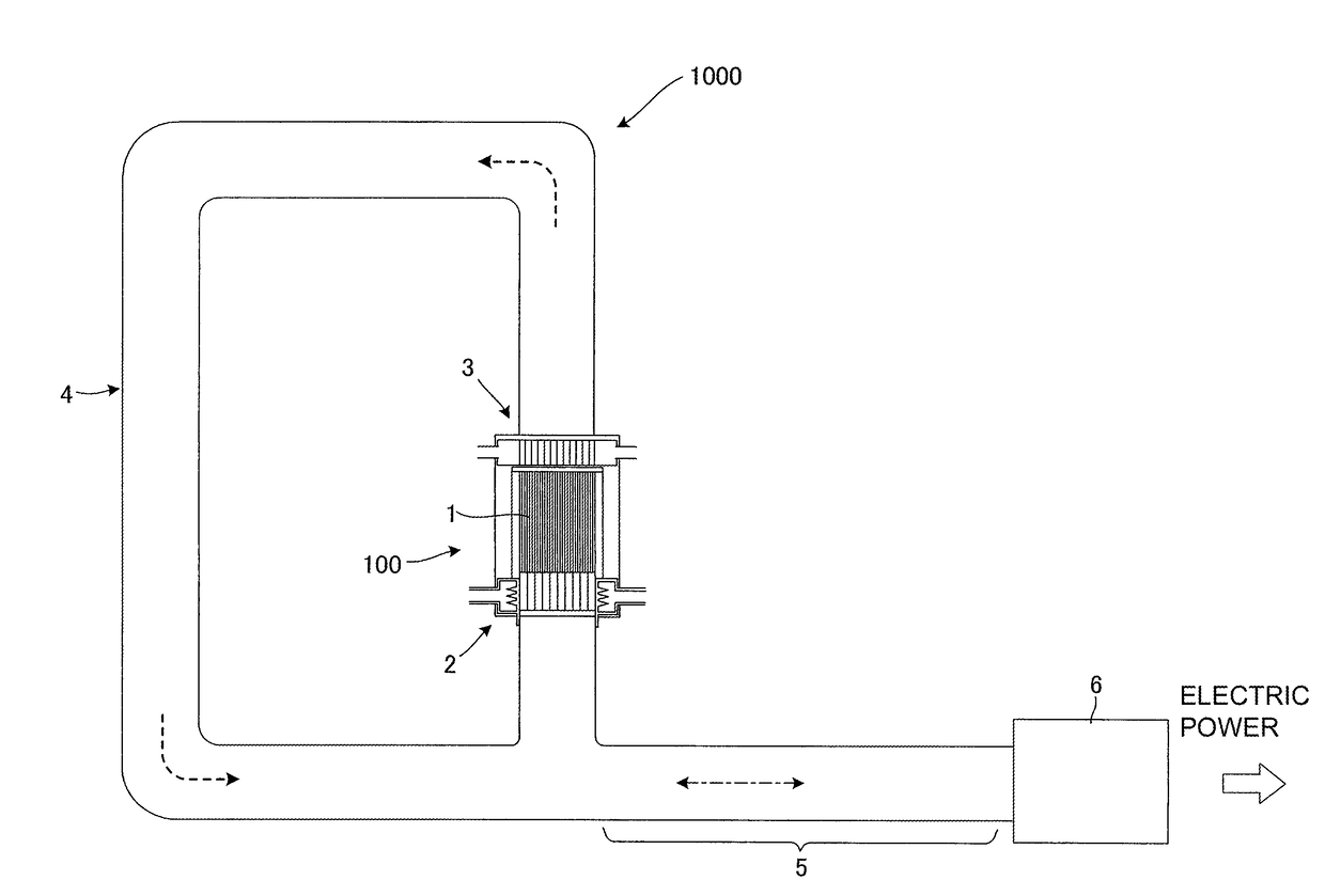
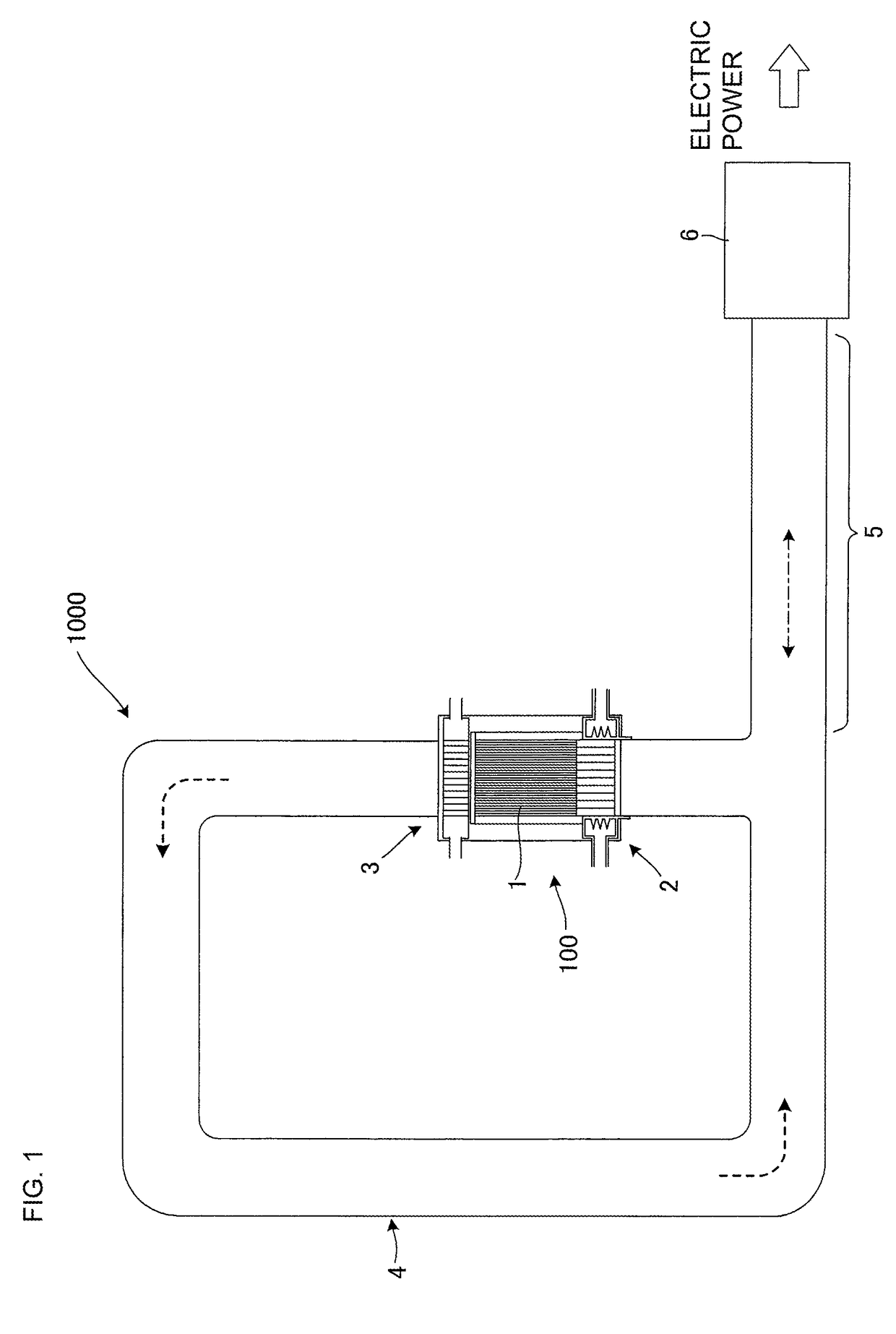
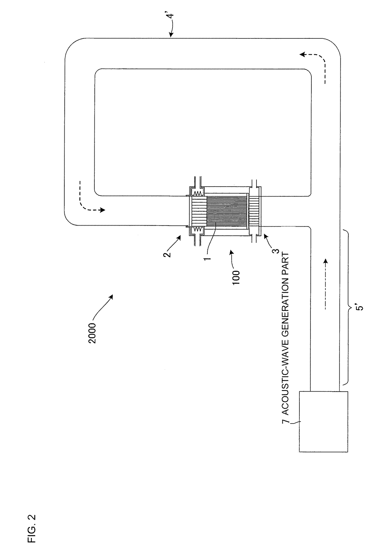
[0017]In view of the above-mentioned circumstances, the present invention aims to provide a heat / acoustic wave conversion unit which includes a heat / acoustic wave conversion component having a honeycomb structure and a pair of heat exchangers to exchange heat with both end parts of this heat / acoustic wave conversion component, and which improves durability and energy conversion efficiency.
[0034]In the heat / acoustic wave conversion unit of the present invention, a heat-exchanging honeycomb structure made of a ceramic material improves durability against heat. Further the ceramic material containing SiC as a main improves the energy conversion efficiency.

Problems solved by technology

However, in order to convert heat of high-temperature fluid such as exhaust gas from an automobile into acoustic-wave energy at high energy conversion efficiency, it is not enough that a honeycomb structure for thermoacoustic effect simply is allowed to have high heat / acoustic wave conversion capability.
In fact, if heat of high-temperature fluid is diffused to the surrounding without transmitting to the end part on the high-temperature side of the honeycomb structure sufficiently, such high heat / acoustic wave conversion capability of the honeycomb structure for thermoacoustic effect cannot be used sufficiently, and it is difficult to achieve high energy efficiency.

Method used


Image

  • Heat/acoustic wave conversion unit
  • Heat/acoustic wave conversion unit
  • Heat/acoustic wave conversion unit

Examples


example 1

[0215]In the heat / acoustic wave conversion unit of Example 1, the heat / acoustic wave conversion component 1 was prepared as follows. Firstly, cordierite forming raw material was used as the ceramic raw material, and 35 parts by mass of dispersing medium, 6 parts by mass of organic binder, and 0.5 parts by mass of dispersing agent were added to 100 parts by mass of the cordierite forming raw material, followed by mixing and kneading to prepare a kneaded material. The cordierite forming raw material used included 38.9 parts by mass of talc of 3 μM in average particle size, 40.7 parts by mass of kaolin of 1 μm in average particle size, 5.9 parts by mass of alumina of 0.3 μm in average particle size, and 11.5 parts by mass of boehmite of 0.5 μM in average particle size. Herein the average particle size refers to a median diameter (d50) in the particle distribution of each raw material.

[0216]Water was used as the dispersing medium. Hydroxypropylmethylcellulose was used as the organic bin...

examples 2 , 3

Examples 2, 3 and Comparative Examples 1 to 3

[0248]Heat / acoustic wave conversion units as Examples 2, 3 and Comparative Examples 1 to 3 were manufactured by the same manufacturing method as that of the manufacturing method of Example 1 as stated above except that a die used for extrusion was different in the manufacturing method of the heat / acoustic wave conversion component, where these heat / acoustic wave conversion units were different from Example 1 only in the values of parameters (hydraulic diameter HD and HD / L) relating to the hydraulic diameter HD of the cells among the fourteen types of parameters as stated above.

[0249]Then, the two experiments 1 and 2 similar to those for Example 1 were conducted for these Examples 2, 3 and Comparative Examples 1 to 3.

examples 4 , 5

Examples 4, 5 and Comparative Examples 4 to 8

[0250]Heat / acoustic wave conversion units as Examples 4, 5 and Comparative Examples 4 to 8 were manufactured by the same manufacturing method as that of the manufacturing method of Example 1 as stated above except that the length of extrusion was different during extrusion in the manufacturing method of the heat / acoustic wave conversion component, where these heat / acoustic wave conversion units were different from Example 1 only in the values of parameters (length L, L / D and HD / L of segment) relating to the length L of the segment among the fourteen types of parameters as stated above.

[0251]Then, the two experiments 1 and 2 similar to those for Example 1 were conducted for these Examples 4, 5 and Comparative Examples 4 to 8.

[0252]The following Table 3 shows the experimental results of Examples 1 to 5 and Comparative Examples 1 to 8 as explained above, together with the values of parameters different from those of Example 1.

[0253]

TABLE 3Ce...


PUM


Abstract

A heat / acoustic wave conversion unit includes a heat / acoustic wave conversion component and two heat exchangers. Hydraulic diameter HD of the cells in the heat / acoustic wave conversion component is 0.4 mm or less, and a ratio HD / L of HD to the length L of the heat / acoustic wave conversion component is from 0.005 to 0.02. One of the heat exchangers includes a heat-exchanging honeycomb structure and an annular tube that surrounds a circumferential face of the heat-exchanging honeycomb structure. The annular tube includes a structure body that is disposed in the channel to increase a contact area with the heated fluid, an inflow port into which the heated fluid flows, and an outflow port through which the heated fluid flows out. At least one of the heat-exchanging honeycomb structure and the structure body is made of a ceramic material that contains SiC as a main component.

Description

[0001]The present application is an application based on JP 2014-192024 filed on Sep. 19, 2014 with Japan Patent Office, the entire contents of which are incorporated herein by reference.BACKGROUND OF THE INVENTION[0002]Field of the Invention[0003]The present invention relates to heat / acoustic wave conversion units. More particularly, the present invention relates to a heat / acoustic wave conversion unit including a heat / acoustic wave conversion component to convert heat and acoustic-wave energy mutually, and a heat exchanger.[0004]Description of the Related Art[0005]Recently society as a whole has been becoming more and more interested in effective use of energy resources, and so various techniques to reuse energy have been developed on a trial basis. Among them, an energy recycling system attracts attention because the acquisition rate (energy efficiency) of the energy acquired is high. The energy recycling system converts heat of high-temperature fluid, such as exhaust gas from au...

Claims


Application Information

Patent Timeline
Patent Type & Authority Patents(United States)
IPC IPC(8): F02G5/02F03G7/00F02G1/02F02G1/043F25B9/14
CPCF02G5/02F02G1/02F02G1/043F03G7/002F25B9/145F02G2243/54F25B2309/1402
Inventor MIYAIRI, YUKIOMIWA, SHINICHIKAWAGUCHI, TATSUONODA, NAOMIDEGUCHI, YUJIMORI, TERUYOSHIHAMATSUKA, KAZUHIKOSUENOBU, HIROYUKIHIRONAGA, MASAYUKIKUMAZAWA, KAZUHIKO
Owner NGK INSULATORS LTD
Learn More