Eureka AIR delivers breakthrough ideas for toughest innovation challenges, trusted by R&D personnel around the world.

System for reducing artifacts in imaging in the presence of a spin-lock radio-frequency field

a radio frequency field and artifact reduction technology, applied in the field of acquiring mr imaging, can solve the problems of increased risk of patient motion, mis-registration artifacts, long imaging time, etc., and achieve the effect of reducing the length of the radiofrequency pulse and improving the preparation of the spin-lock magnetic field

Active Publication Date: 2017-09-12
SIEMENS HEALTHCARE GMBH
View PDF8 Cites 0 Cited by
  • Summary
  • Abstract
  • Description
  • Claims
  • Application Information

AI Technical Summary

Benefits of technology

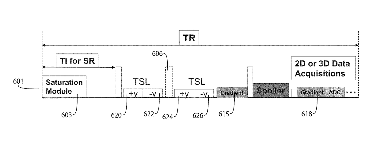
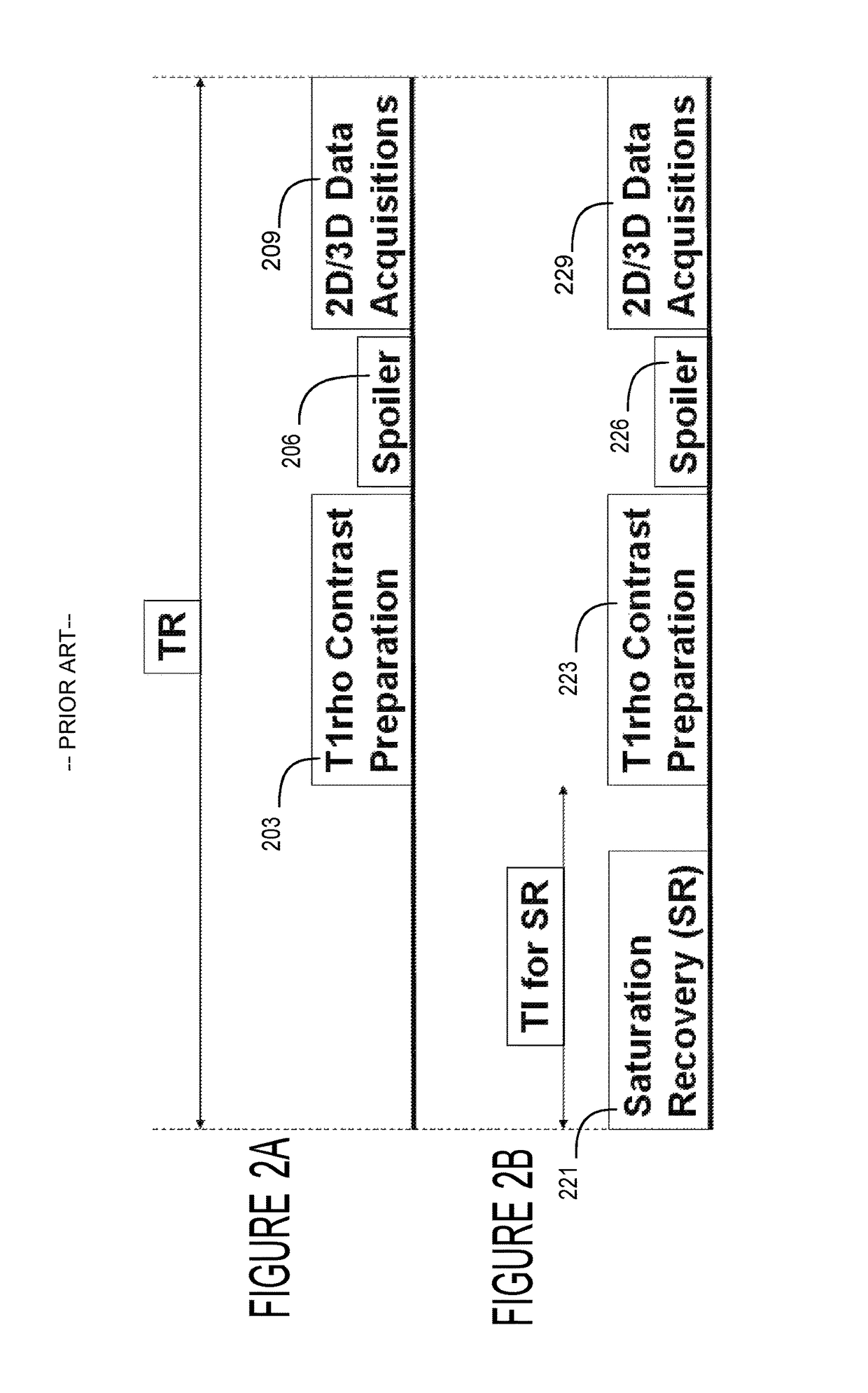
[0004]A system improves spin-lock magnetic field preparation by providing a pulse sequence that reduces length of a radiofrequency (RF) pulse needed to generate required T1rho contrast as well as sensitivity to static magnet field (B0) and also dynamic transmission RF field (B1) inhomogeneity. A system acquires MR image data of a portion of patient anatomy associated with spin lattice relaxation time in a rotating frame using an RF (Radio Frequency) signal generator and a magnetic field gradient generator. The RF (Radio Frequency) signal generator generates RF excitation pulses in anatomy and enables subsequent acquisition of associated RF echo data. The magnetic field gradient generator generates anatomical volume select magnetic field gradients for phase encoding and readout RF data acquisition in a three dimensional (3D) anatomical volume. The RF signal generator and the gradient generator use in order, a saturation pulse, a T1 spin lattice relaxation rotating frame preparation pulse sequence and a spoiler gradient, in acquiring image data of the 3D volume showing luminance contrast associated with T1 spin lattice relaxation in a rotating frame.

Problems solved by technology

Attempts to reduce resulting artifacts involve longer imaging time and increased risk of patient motion and mis-registration artifacts.

Method used


Image

  • System for reducing artifacts in imaging in the presence of a spin-lock radio-frequency field
  • System for reducing artifacts in imaging in the presence of a spin-lock radio-frequency field
  • System for reducing artifacts in imaging in the presence of a spin-lock radio-frequency field

Examples


Embodiment Construction

[0012]A system improves spin-lock magnetic field preparation using a pulse sequence that reduces length of a radiofrequency (RF) pulse needed to generate image contrast due to T1rho as well as sensitivity to static magnet field (B0) and also dynamic transmission RF field (B1) inhomogeneity. T1 rho image contrast is due to spin lattice relaxation time constant in the rotating frame and decay of the transverse magnetization in the presence of a “spin-lock” radio-frequency field.

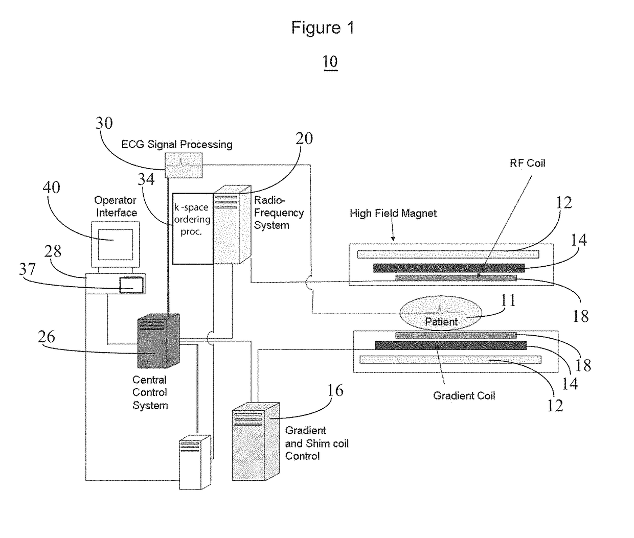
[0013]FIG. 1 shows system 10 for acquiring MR imaging data of a portion of patient anatomy associated with spin lattice relaxation time in a rotating frame. In system 10, magnet 12 creates a static base magnetic field in the body of patient 11 to be imaged and positioned on a table. Within the magnet system are gradient coils 14 for producing position dependent magnetic field gradients superimposed on the static magnetic field. Gradient coils 14, in response to gradient signals supplied thereto by a gradient an...


PUM


Abstract

A system acquires MR image data of a portion of patient anatomy associated with spin lattice relaxation time in a rotating frame using an RF (Radio Frequency) signal generator and a magnetic field gradient generator. The RF (Radio Frequency) signal generator generates RF excitation pulses in anatomy and enables subsequent acquisition of associated RF echo data. The magnetic field gradient generator generates anatomical volume select magnetic field gradients for phase encoding and readout RF data acquisition in a three dimensional (3D) anatomical volume. The RF signal generator and the gradient generator use in order, a saturation pulse, a T1 spin lattice relaxation rotating frame preparation pulse sequence and a spoiler gradient, in acquiring image data of the 3D volume showing luminance contrast associated with T1 spin lattice relaxation in a rotating frame.

Description

[0001]This is a non-provisional application of provisional application Ser. No. 61 / 673,275 filed Jul. 19, 2012, by K. Liu et al.FIELD OF THE INVENTION[0002]This invention concerns a system for acquiring MR imaging data of a portion of patient anatomy associated with spin lattice relaxation time in a rotating frame.BACKGROUND OF THE INVENTION[0003]Known systems for spin-lock magnetic field preparation that generate T1rho contrast associated with a spin lattice relaxation time constant in a rotating frame, are limited by SAR (Specific Absorption Rate) constraints. This is because a long radiofrequency (RF) pulse is needed to generate the required T1rho contrast. The known systems are also vulnerable to inhomogeneity in the static magnet field (B0) and also a dynamic transmission RF field (B1). Attempts to reduce resulting artifacts involve longer imaging time and increased risk of patient motion and mis-registration artifacts. A system according to invention principles addresses these...

Claims


Application Information

Patent Timeline
Patent Type & Authority Patents(United States)
IPC IPC(8): G01V3/00G01R33/561G01R33/56G01R33/565
CPCG01R33/561G01R33/5602G01R33/5659G01R33/56563
Inventor LIU, KECHENGZHAO, TIEJUN
Owner SIEMENS HEALTHCARE GMBH
Why Eureka
Eureka Blog
Learn More