
Stacked planar capacitors with scaled EOT

Inactive Publication Date: 2017-09-12
IBM CORP
View PDF16 Cites 21 Cited by
  • Summary
  • Abstract
  • Description
  • Claims
  • Application Information

AI Technical Summary

Benefits of technology

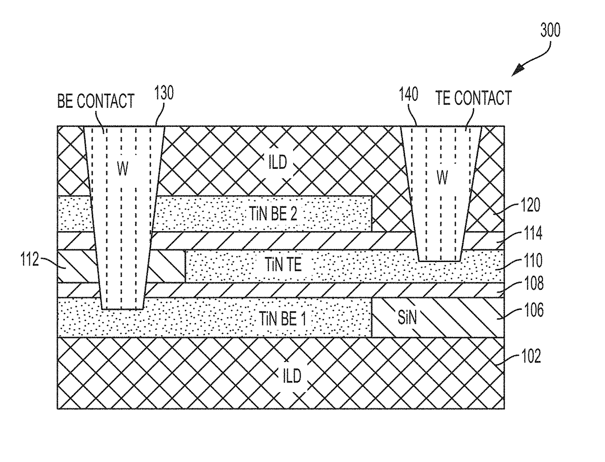
The present invention introduces a new type of 3D via stacked planar capacitor that requires less substrate space and offers better reliability than traditional capacitors. Additionally, methods are provided for creating this new capacitor.

Problems solved by technology

However, this method requires electrical routing between the capacitors and microprocessor, which increases thickness and cost of the package substrate.
Furthermore, the electrical routing to the capacitors on the package increases inductance.
However, the capacitance output of gate oxide or finger comb capacitors is limited by high voltage breakdown and layout factors.
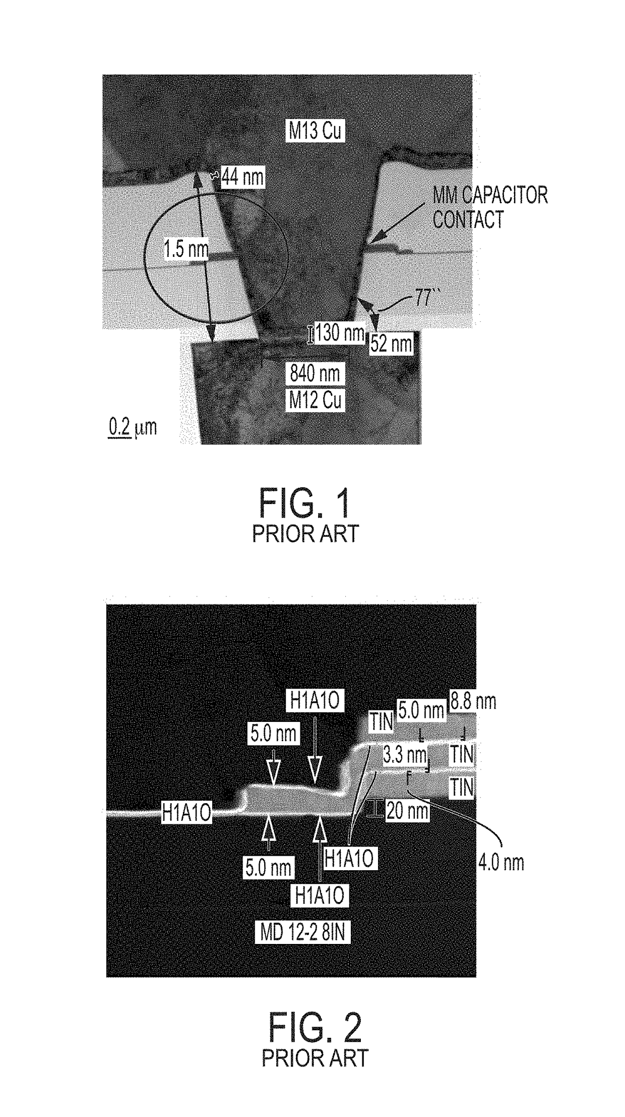
However, these types of devices are prone to leakage and reliability issues due to the step height differences in the dielectric of the prior art capacitor structures, which makes multiple stacking of the same structure difficult.
With regard to Ng, the dielectric between electrodes is not flat at the edges, which leads to current leakage and reliability issues.
Current leakage necessitates an increase in dielectric thickness, which is undesirable for capacitance enhancement and higher chip area utilization.
As shown more clearly in FIG. 2, the step height at the edge can result in weak spots in the high k dielectric layer resulting in current leakage and reliability issues.
Moreover, the step height makes multiple stacking of the same structure difficult.

Method used


Image

  • Stacked planar capacitors with scaled EOT
  • Stacked planar capacitors with scaled EOT
  • Stacked planar capacitors with scaled EOT

Examples


Embodiment Construction

[0028]The present invention will now be described more fully hereinafter with reference to the accompanying drawings in which preferred embodiments of the invention are shown. This invention may, however, be embodied in many different forms and should not be construed as limited to the illustrated embodiments set forth herein. Rather, these embodiments are provided so that this disclosure will be thorough and complete, and will fully convey the scope of the invention to those skilled in the art. Like numerals refer to like features throughout.

[0029]It will be understood that when an element, such as a layer, is referred to as being “on” or “over” another element, it can be directly on the other element or intervening elements may also be present. In contrast, when an element is referred to as being “directly on” or “directly over” another element, there are no intervening elements present.

[0030]Disclosed herein are methods and structures for forming one or more stacked planar electr...


PUM


Abstract

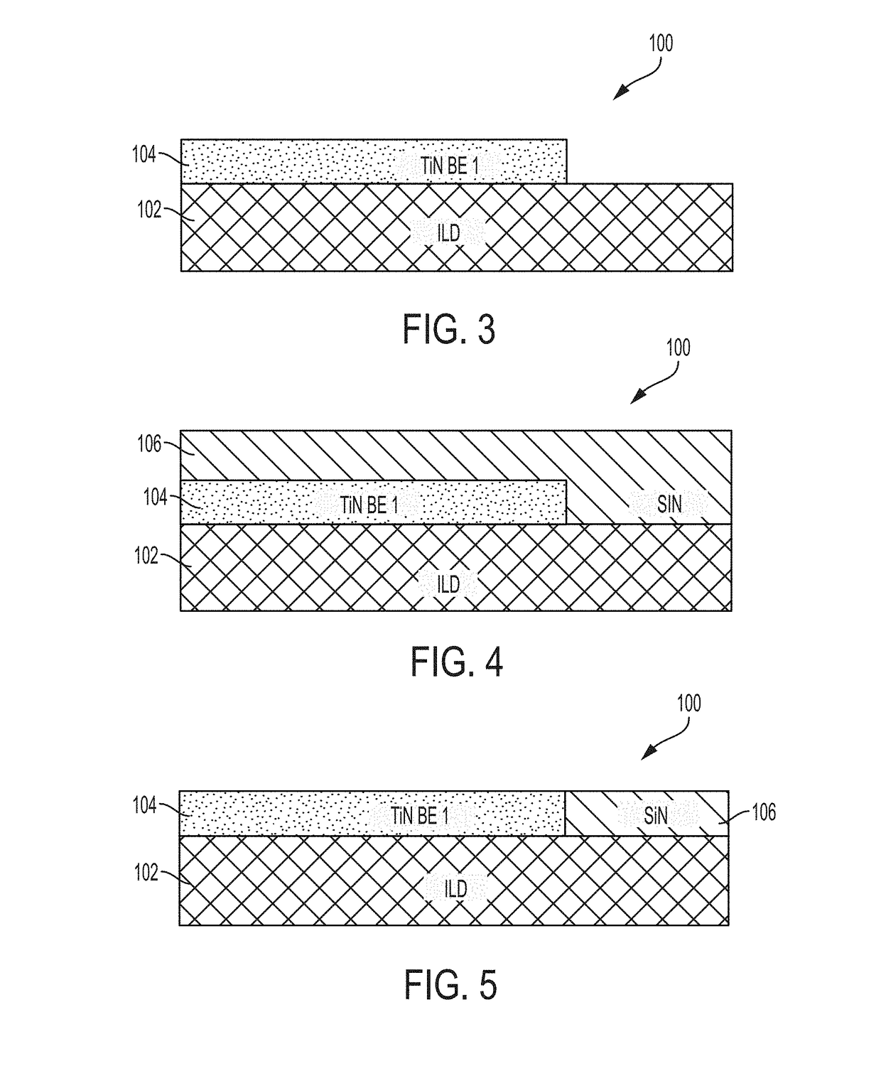
Stacked planar capacitor structures and methods of fabricating the same generally include stacking two or more capacitors with three electrodes by sharing a middle electrode, wherein each capacitor has a different area. The stacked structure does not include step heights, which permits fabrication of multiple structures where desired.

Description

BACKGROUND[0001]The present invention relates to a capacitor structure for an integrated circuit and a method of fabrication thereof, with particular application to stacked planar capacitors for low leakage applications.[0002]Modern integrated circuits, such as microprocessors, use numerous passive components such as resistors and capacitors. In one application, decoupling capacitors are used to reduce undesired noise signals from the power supply. For example, conventional embedded DRAM and decoupling capacitors typically utilize three dimensional structures to increase the surface area and to obtain large capacitance values. One method of adding decoupling capacitors to the microprocessor is by forming them on the package substrate. However, this method requires electrical routing between the capacitors and microprocessor, which increases thickness and cost of the package substrate. Furthermore, the electrical routing to the capacitors on the package increases inductance.[0003]Dec...

Claims


Application Information

Patent Timeline
IPC IPC(8): H01L49/02H01L21/20H01L29/06H01L23/522H01L21/768H01L23/532
CPCH01L28/75H01L29/0649H01L21/76879H01L21/76883H01L23/5226H01L23/53257H01L23/5223
Inventor ANDO, TAKASHICLEVENGER, LAWRENCE A.JAGANNATHAN, HEMANTHQUON, ROGER A.
Owner IBM CORP
Learn More