Device and method for fastener element retention and installation

a technology of fastener and element, applied in the direction of wrenches, power driven tools, screwdrivers, etc., can solve the problems of further adding undesirable length to the fastener, feature adding cost, etc., and achieve the effect of improving productivity and improving the productivity of the installation of various fasteners

Active Publication Date: 2017-09-19
KOCH KEVIN SCOTT
View PDF68 Cites 8 Cited by
  • Summary
  • Abstract
  • Description
  • Claims
  • Application Information

AI Technical Summary

Benefits of technology

[0023]A method and a device are disclosed which seek to improve productivity of the installation of various fasteners. This improved productivity may be achieved by allowing a fastener to be loaded into a device as is shown in the descriptions to follow such that no direct manipulation of said device is required during the loading of a fastener, the installation of that fastener, the disengagement of said device from the installed fastener, or before loading a subsequent fastener.
[0024]It is a further object of the present invention to utilize a mechanical means of holding fasteners securely, such that a fastener loaded into a device as depicted in the descriptions below will resist significant axial and bending moment forces about any axis without becoming disengaged from the said device during the initial phase of fastener installation to enhance productive installation of fasteners of all types.
[0025]It is a further object of the invention to provide a means by which thrust may be transmitted directly from a driving tool connected to a device of the present invention, through said device and to a fastener without the thrust force applied to the fastener being transmitted through a spring to increase the thrust transmission ability.
[0027]It is a further object of one embodiment of this invention to provide a clutch mechanism for disengaging transmission of torque to a fastener at an adjustable depth for quick and consistent fastener installation.
[0029]Furthermore, in some fastening applications such as installation of drill-point and other self-drilling screws a significant amount of thrust must be applied to the fastener while it is being driven, typically by a rotary tool. Generally, that fastener will be driven numerous rotations prior to engaging the work sufficiently that buckling between a fastener and the driver is no longer a concern. Further, these screws are commonly installed in large volumes during construction activities. They thus represent particularly demanding applications where the limitations of current methods are amplified and the benefits of the present invention are highly impactful.
[0033]The device of the present invention can also be utilized to remove fasteners and it provides unique benefits to such. When removing a fastener, a user would begin with the device in the open configuration, precisely the same configuration the device is in before a fastener is loaded prior to install. As the fastener is backed out from its installed position, the device and fastener will go through the same configurations of the device shown for installation, but in the reverse order. A benefit to the removal of a fastener is that significant thrust can be applied to the fastener in the direction pointing away from the work surface the fastener is installed in. This is of significant benefit for removing drill-point screws where the screw threads disrupt the fastener receiving material after the drill point creates a hole, causing the clear passage diameter of the fastener's hole to be smaller than the drill tip. Removal of these screws may thus require significant rearward thrust, often supplied by a pliers or similar tool. After removing a fastener in this sort of arrangement, the outer cam sleeve will need to be pulled away from the distal end of the tool to release the fastener.

Problems solved by technology

Many basic fasteners do not have such a point to facilitate such alignment, and typically adding such a feature adds cost to fasteners and it may further add undesirable length to that fastener.

Method used


Image

  • Device and method for fastener element retention and installation
  • Device and method for fastener element retention and installation
  • Device and method for fastener element retention and installation

Examples


first embodiment

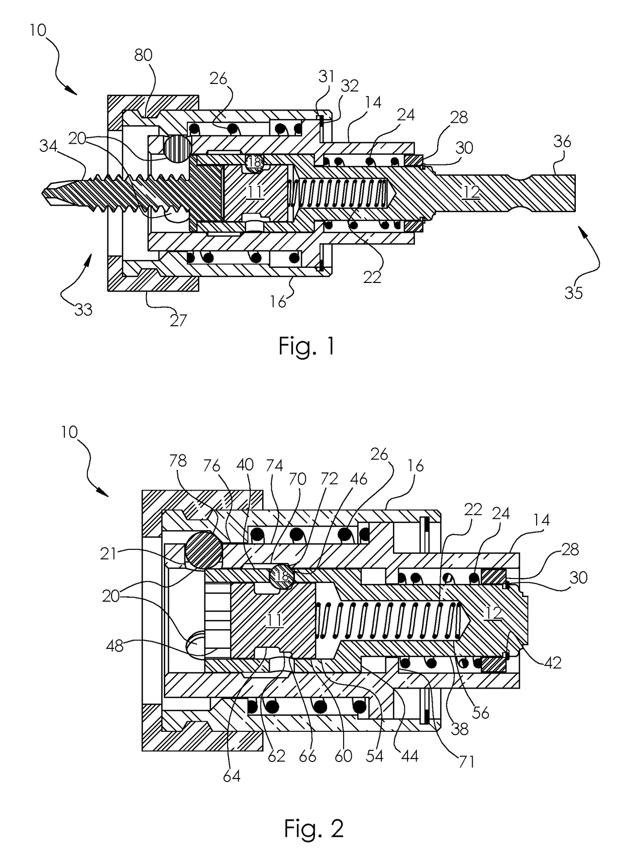
[0056]FIG. 2 is a cross-sectional view of a first embodiment illustrated generally as 10, configured in the unloaded position, ready for a fastener to be loaded. In this figure, previously shown shank 36 has been cropped off the proximal side of the device as it may take the form of many conventional shank styles, the specifics of which are not central to the function of this embodiment. The distal end of drive bit 12 has a bore 48 for receiving the external drive geometry of a fastener. The trigger shuttle 11 is slidably located in a longitudinal bore 54 within bit 12. The trigger shuttle 11 has a proximal section 60 of a first outer diameter which is slightly smaller than the diameter of bore 54 to allow relative sliding motion between trigger shuttle 11 and bit 12. Shuttle 11 includes a section 62 of a second diameter distal to section 60 and also of a smaller diameter than 60. A third section 64 is distal to section 62 and section 64 has a diameter which is smaller than section ...

third embodiment

[0085]the invention could modify the mechanics of device 138 shown in FIG. 10 to utilize smaller balls 20 thereby reducing the length and diameter of such a device whereby significantly increasing radial clearance between the shank of mating fastener 134 and balls 20. This will reduce somewhat the ability of device 138 to engage and align the two mating fasteners 134 and 132, but the many previously mentioned advantages to the current invention would be retained.

fourth embodiment

[0086]FIG. 11 is a section view of a fourth embodiment for fasteners containing geometric drive depressions, generally illustrated as device 160, which is shown here in an unloaded state. Device 160 includes a fastener 161, a bit holder 162, and a bit insert 164 which will include drive geometry to interface with a fastener such as a cruciform, straight blade, hexagon, hex-lobular, or square drive. Bit insert 164 has a circumferential groove in which a retaining ring 188 will retain the bit insert 164 within bit holder 162 under normal operating conditions, but will also allow removal to change to an alternate bit insert 164. Located within bit holder 162 is a spacer ball 180, intermediate ball 182 and a plurality of trigger balls 184. A compression spring (not shown) will react between bore face 206 and ball 182 to urge ball 182 and subsequently ball 180 and bit insert 164 forward towards the fastener receiving end of device 160. Sleeve 166 contains an internal groove 200 for inter...


PUM

PropertyMeasurementUnit
forcesaaaaaaaaaa
storing energyaaaaaaaaaa
stored energyaaaaaaaaaa

Abstract

A method and a device are disclosed which seek to improve productivity of the installation of fasteners. This improved productivity is achieved by holding a fastener to a driving tool with a mechanical means for a substantial portion of an installation sequence to prevent nuisance disengagement between fasteners and their driving means including dropping of fasteners early in an installation cycle. The productivity of this fastener holding approach is best realized by allowing a streamlined operation with little interaction between the fastener driving device and an operator. Specifically, a fastener installation device is described which requires no direct manipulation of said device during the sequence of loading a fastener into said device, installation of said fastener with said device, disengagement of said device from said fastener to allow complete installation of said fastener, and loading a subsequent fastener.

Description

CROSS REFERENCE TO RELATED APPLICATIONS[0001]This application claims the benefit of the filing date of the provisional patent application having Ser. No. 62 / 185,571 filed Jun. 27, 2015.BACKGROUND OF THE INVENTION[0002]This section provides background information related to the present disclosure which is not necessarily prior art.[0003]Fastener elements such as a screw, nut, bolt, nail, rivet, etc., hereinafter referred to as fasteners, are used to join components together in a myriad of applications. With conventional installation tools, a fastener will engage either a drive socket for fasteners with external driving geometry, such as a hex head bolt, or the fastener will engage a drive bit for fasteners with internal driving geometry, such as a slot, cruciform or internal hex bore. Fasteners easily disengage from these conventional tools and thus an installer may steady a fastener in some fashion during the first phase of initial install until the fastener is installed to a degree...

Claims


Application Information

Patent Timeline
Patent Type & Authority Patents(United States)
IPC IPC(8): B25B23/10B25B21/00B25B23/12B25B23/00
CPCB25B23/12B25B23/0035B25B23/10Y10T29/49826Y10T29/49833B25B23/108
Inventor KOCH, KEVIN SCOTT
Owner KOCH KEVIN SCOTT
Why Eureka
Try Eureka