Methods and systems for automated robotic movement

Active Publication Date: 2017-09-19
BOBSWEEP
View PDF17 Cites 16 Cited by
  • Summary
  • Abstract
  • Description
  • Claims
  • Application Information

AI Technical Summary

Benefits of technology

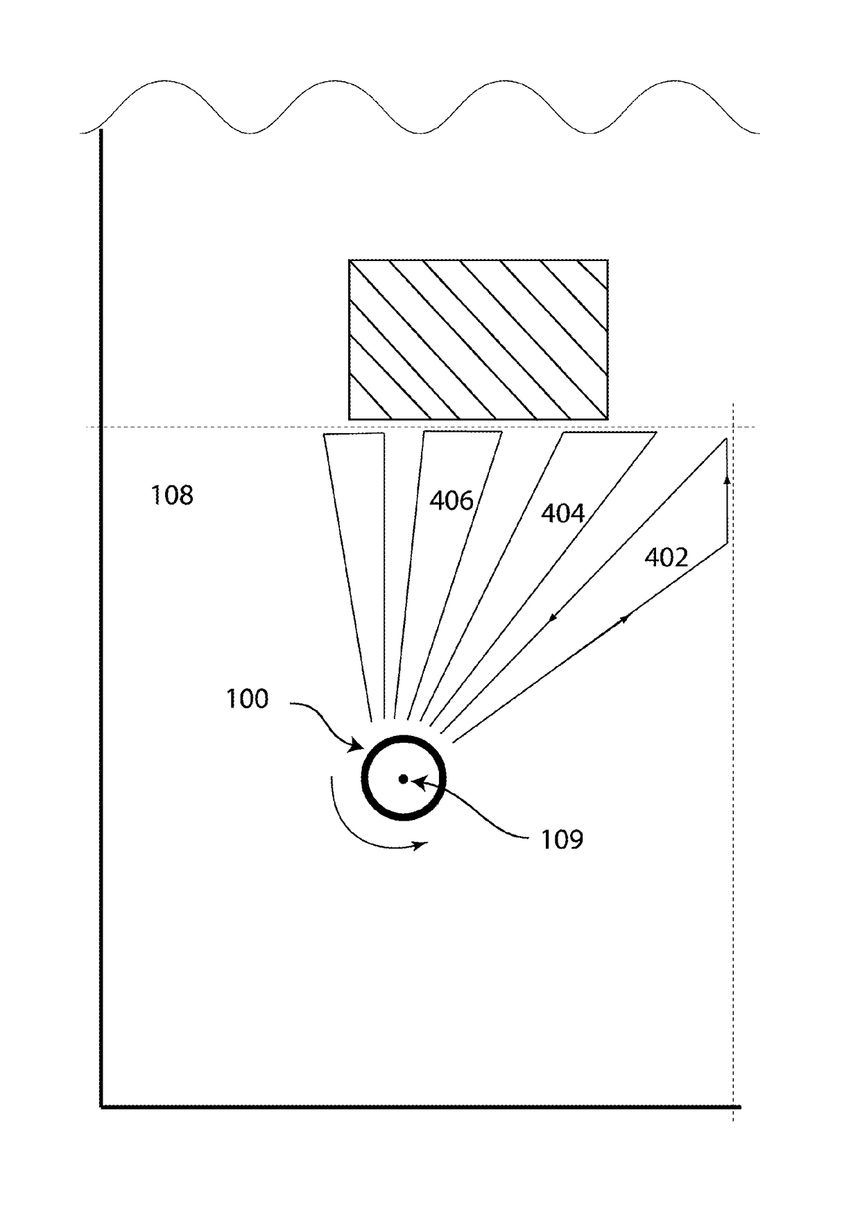
[0025]In an embodiment, an asterisk path mode may be used. In an embodiment, the asterisk path mode may be utilized if the robotic device encounters a number of problems during completion of its job while running the daisy path mode. Asterisk path mode in some embodiments, may be, but not necessarily, a last resort among the three introduced patterns due to its inherent redundancy while delivering the highest probability for effective completion in areas with high number of unforeseen obstacles. Asterisk cleaning method is based on the same collision-mitigation concepts described above, however in this method, the robotic device will first measure a linear path from the center point to the nearest obstacle, then clean along this path up to the obstacle and back to center point on the same or substantially the same line. This increases the probability that each time the robotic device undertakes a new path, it is almost certainly substantially collision-free. In operation, the robotic device continues the pattern, traveling in linear radial paths around the center point, until the job is completed.
[0026]In an embodiment, a complimentary cleaning pattern h

Problems solved by technology

It has always been a challenge with autonomous cleaning robots to ensure full coverage of a working area in a timely manner.
Several efforts have been made to address this challenge, most of which are either too expensive or impractical for use in a typical consumer's daily application.
Each of the said technologies has its own limits and problems, such as expensive technology and complications of application.
In order to utilize the navigation system, however, the robot must see at least four of the bar codes simultaneously, which creates a significant operational problem.
The use of rotating laser rangefinders on the robotic device has a few downsides, one of which is the mechanical nature of solution.
Mechanical

Method used


Image

  • Methods and systems for automated robotic movement
  • Methods and systems for automated robotic movement
  • Methods and systems for automated robotic movement

Examples


Example

[0051]As will be appreciated by one skilled in the art, the present invention may be a system, a method, an apparatus, and / or a computer program product. The computer program product may include a computer readable storage medium (or media) having computer readable program instructions thereon for causing a processor to carry out features of the present invention. The computer readable storage medium can be a tangible device that can retain and store instructions for use by an instruction execution device. The computer readable storage medium may be, for example, but is not limited to, an electronic storage device, a magnetic storage device, an optical storage device, an electromagnetic storage device, a semiconductor storage device, or any suitable combination of the foregoing. A non-exhaustive list of more specific examples of the computer readable storage medium includes the following: a portable computer diskette, a hard disk, a random access memory (RAM), a read-only memory (RO...


PUM


Abstract

Methods for automated robotic movement for a robotic device using an electronic computing device are presented, the methods including: causing the electronic computing device to establish a working zone; measuring distances to all obstacles in the working zone thereby detecting all obstacles in the working zone; establishing a coverage path that accounts for all detected obstacles; executing the coverage path such the robotic device covers the working zone at least once; if a new obstacle is detected, establishing an adapted coverage path that accounts for the new obstacle; and executing the adapted coverage path. In some embodiments, methods further include: bypassing the new obstacle; and returning to the coverage path.

Description

FIELD OF INVENTION[0001]The present invention generally relates to automated robotic path generation for moving a robotic device autonomously, and device and systems using the same.BACKGROUND[0002]It has always been a challenge with autonomous cleaning robots to ensure full coverage of a working area in a timely manner. Several efforts have been made to address this challenge, most of which are either too expensive or impractical for use in a typical consumer's daily application.[0003]A cleaning robot's performance is measured by the amount of cleaning it does relative to the area that it visits in a given amount of time. If a cleaning robot relies purely on random movement, then its performance decreases relative to the amount of coverage as a function of time. In other words, efficiency (E) approaches zero when time (T) approaches infinity.[0004]One way to optimize the robot's cleaning behavior is to equalize the cleaning rate with the coverage rate. To accomplish this, there is a...

Claims


Application Information

Patent Timeline
IPC IPC(8): B25J9/16G05D1/02
CPCB25J9/1666B25J9/1605B25J9/1694G05D1/0238G05D1/0242G05D1/0251Y10S901/01Y10S901/09G05D2201/0215B25J9/1664G05D1/0219G05D2201/0203
Inventor EBRAHIMI AFROUZI, ALIEBRAHIMI AFROUZI, MASIHMEHRNIA, SOROUSHEBRAHIMI AFROUZI, AMINBAKOOSHLI, AZADEH AFSHAR
Owner BOBSWEEP
Why Eureka
Try Eureka