Pulse modulated passive intermodulation (PIM) measuring instrument with reduced noise floor

a passive intermodulation and measuring instrument technology, applied in the field of systems and methods for measuring passive intermodulation (pim), can solve the problems of interference, interference, and the operator of wireless communication systems, and reduce the sensitivity of a cell or block calls,

Active Publication Date: 2017-09-19
ANRITSU CO
View PDF48 Cites 26 Cited by
  • Summary
  • Abstract
  • Description
  • Claims
  • Application Information

AI Technical Summary

Benefits of technology

[0007]In an embodiment, a method for calculating passive intermodulation (PIM) associated with a device under test (DUT) includes generating a test signal using a measuring instrument and obtaining measurements of PIM generated at the DUT. The test signal comprises two or more tones each amplified to a target output power by a respective amplifier according to a duty cycle. Measurements are obtained by the measuring instrument during an active portion of each duty cycle over a sweep of frequencies. PIM is calculated for the DUT by averaging a plurality of measurements obtained for each frequency from the sweep of frequencies. The duty cycle is determined based on the target output power. In an embodiment, the duty cycle is further determined based on a receiver sensitivity of the measuring instrument. In an embodiment, the duty cycle is determined using an equation or a look-up table. The determination of duty cycle varies inversely with the target output power. In an embedment, the determination of duty cycle is varied with the target output power so that an average power consumed by the measuring instrument is approximately constant.
[0008]In an embodiment, a measuring instrument for performing methods in accordance with the present invention includes a signal generator for generating test signals and a computer readable non-transitory storage medium and processor operating thereon, wherein the computer readable non-transitory storage medium includes instructions for measuring PIM generated at a DUT. The computer readable non-transitory storage medium further includes instructions that when executed in response to user input cause the measuring instrument to generate a test signal comprising two or more tones each amplified to a target output power by a respective amplifier according to a duty cycle, obtain measurements of PIM during an active portion of each duty cycle over a sweep of frequencies and calculate PIM associated with the DUT by averaging a plurality of measurements obtained for each frequency from the sweep of frequencies. The duty cycle is determined based on the target output power.

Problems solved by technology

Passive intermodulation (PIM), resulting from the non-linear mixing of two or more frequencies in a passive device such as a connector or cable, can be problematic for operators of wireless communication systems.
In a cellular network, PIM creates interference that can reduce a receive sensitivity of a cell or block calls.
This interference can affect the cell that creates it, as well as other nearby receivers.
PIM can be a serious issue for operators of wireless communication systems wanting to maximize a system's reliability, data rate, capacity, and return on investment.
High-speed digital data communications have further increased the problematic nature of PIM.
PIM has surfaced as a problem for wireless data transmission using modern standards including Long-Term Evolution (LTE), Global System for Mobile Communications (GSM), Advanced Wireless Service (AWS) and Personal Communication Service (PCS) standards.
As cell usage and throughput grow, the peak power produced by new digital modulations increases dramatically, potentially contributing heavily to PIM problems.

Method used


Image

  • Pulse modulated passive intermodulation (PIM) measuring instrument with reduced noise floor
  • Pulse modulated passive intermodulation (PIM) measuring instrument with reduced noise floor
  • Pulse modulated passive intermodulation (PIM) measuring instrument with reduced noise floor

Examples


Embodiment Construction

[0012]The following description is of the best modes presently contemplated for practicing various embodiments of the present invention. The description is not to be taken in a limiting sense but is made merely for the purpose of describing the general principles of the invention. The scope of the invention should be ascertained with reference to the claims. In the description of the invention that follows, like numerals or reference designators will be used to refer to like parts or elements throughout. Like parts or elements may be described in a single embodiment, or they may be described in multiple embodiments.

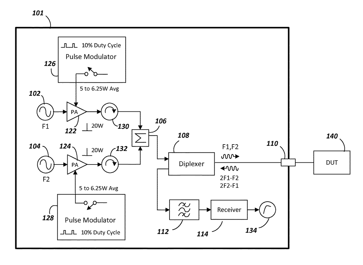
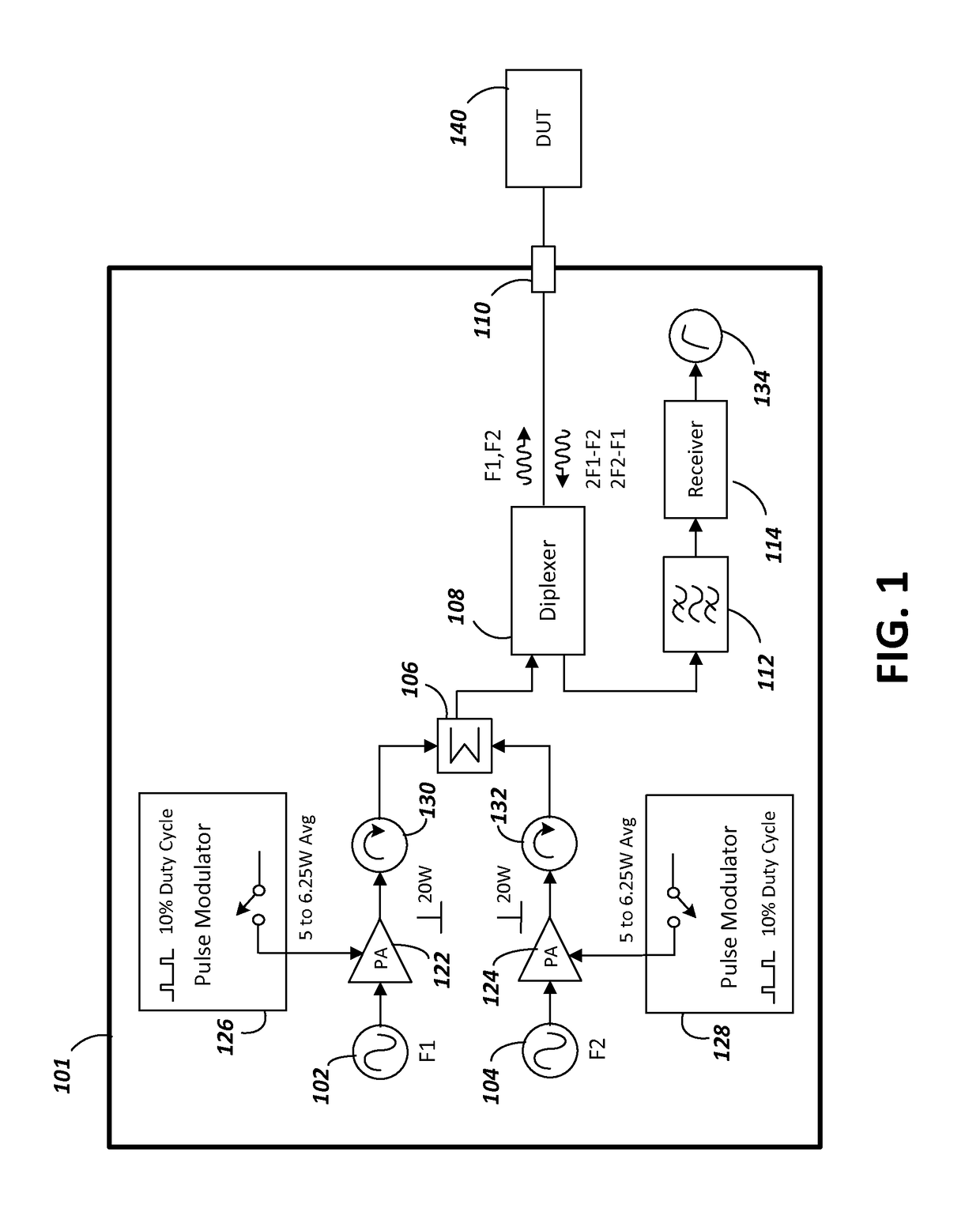
[0013]FIG. 1 is a simplified, block diagram of an instrument 101 usable for measuring PIM (referred to hereinafter as a measuring instrument). The measuring instrument comprises two signal sources, with a first signal source 102 generating a first tone at frequency F1 and a second signal source 104 generating a second tone at frequency F2. The first tone is amplified by a...


PUM


Abstract

In an embodiment, a method for measuring passive intermodulation (PIM) associated with a device under test (DUT) includes generating a test signal using a measuring instrument and obtaining measurements of PIM for the DUT. The test signal comprises two or more tones each amplified to a target output power by a respective amplifier according to a duty cycle. Measurements are obtained by the measuring instrument during an active portion of each duty cycle over a sweep of frequencies. PIM is calculated for the DUT by averaging a plurality of measurements obtained for each frequency from the sweep of frequencies. The duty cycle is determined based on the target output power.

Description

BACKGROUND[0001]Technical Field[0002]The present invention relates generally to systems and methods for measuring passive intermodulation (PIM).[0003]Related Art[0004]Passive intermodulation (PIM), resulting from the non-linear mixing of two or more frequencies in a passive device such as a connector or cable, can be problematic for operators of wireless communication systems. PIM can appear, for example, as existing equipment ages, when new carriers are co-located, when new carriers are overlaid (diplexed) into old antenna runs, and when new equipment is installed. In a cellular network, PIM creates interference that can reduce a receive sensitivity of a cell or block calls. This interference can affect the cell that creates it, as well as other nearby receivers. PIM can be a serious issue for operators of wireless communication systems wanting to maximize a system's reliability, data rate, capacity, and return on investment.[0005]High-speed digital data communications have further...

Claims


Application Information

Patent Timeline
Patent Type & Authority Patents(United States)
IPC IPC(8): H04B17/00G01R31/11H04B17/17H04B17/29G01R31/00G01R31/12G01R31/08
CPCH04B17/0085G01R31/001G01R31/11H04B17/17H04B17/29G01R31/088G01R31/1272H04B17/26
Inventor BRADLEY, DONALD ANTHONY
Owner ANRITSU CO
Why Eureka
Try Eureka