Multiplatform GMTI radar with adaptive clutter suppression

a radar and clutter suppression technology, applied in the field of radar processing systems, can solve the problems of limiting factors of gmti radar, slow-moving target background clutter, and mdv is primarily limited, so as to increase the electrical size of the radar antenna aperture, reduce mdv, and achieve the effect of large effective electrical apertur

Active Publication Date: 2017-09-26
SRC INC
View PDF14 Cites 7 Cited by
  • Summary
  • Abstract
  • Description
  • Claims
  • Application Information

AI Technical Summary

Benefits of technology

[0014]The present invention addresses the needs described above by providing a multiplatform GMTI radar with adaptive clutter suppression that is configured to increase the electrical size of the radar antenna aperture using a distributed antenna array via multiple mobile platforms. The present invention substantially reduces the MDV by making the effective electrical aperture very large. This is accomplished by combining two or more mobile radars (disposed on separate ground vehicle, airborne or spaceborne platforms) so that they function as one. The associated large aperture allows cancellation of mainlobe clutter without suffering severe target-gain loss. Most importantly the multiplatform GMTI radar of the present invention is configured to detect ground moving targets with very small minimum detectable velocities without requiring that the relative positions of the antenna phase centers be accurately tracked.
[0023]In yet another embodiment, the clutter signal is substantially equal to y(θc)=x1(θc)+w*x2(θc), where x1(θc) and x2(θc) are the plurality of first clutter signals and the plurality of second clutter signals, respectively, and θc denotes the angle of a clutter direction vector relative to the distributed array boresight, and wherein w* is the complex conjugate of the complex weight w that maintains target signal strength while minimizing the mean square value of the clutter signal.
[0032]In yet another embodiment, the clutter signal is substantially equal to y(θc)=x1(θc)+w*x2(θc), where x1(θc) and x2(θc) are the plurality of first clutter signals and the plurality of second clutter signals, respectively, and θc denotes the angle of a clutter direction vector relative to the distributed array boresight, and wherein w* is the complex conjugate of the complex weight that maintains target signal strength while minimizing the mean square value of the clutter voltage.
[0039]In yet another version, the application of the weight vector w to a signal vector automatically coheres the plurality of first clutter signals and the plurality of second clutter signals to substantially cancel the plurality of first clutter signals and the plurality of second clutter signals and maintain the target signal strength.

Problems solved by technology

Because resources are limited, military commanders must use their assets smartly and efficiently.
One of the drawbacks with GMTI radar relates to its ability (or inability) to distinguish slow-moving targets from background clutter.
A limiting factor of GMTI radar arises from the fact that the MDV is primarily limited by the electrical size of the radar antenna aperture; sharper angle filtering requires a larger antenna aperture.
However, since the GMTI radar (and its antenna) is part of the aircraft's payload, the size of the antenna aperture is strictly limited by the size of the aircraft platform itself.
One obvious drawback to this approach relates to the fact that the system is immobile during usage.
Thus, a major drawback to mobile multiplatform GMTI radar relates to the fact that the relative positions of the platform antenna phase centers must be tracked to a small fraction of a wavelength.
Such tracking accuracies are very difficult, if not impossible, to achieve with moving platforms at radar frequencies.

Method used


Image

  • Multiplatform GMTI radar with adaptive clutter suppression
  • Multiplatform GMTI radar with adaptive clutter suppression
  • Multiplatform GMTI radar with adaptive clutter suppression

Examples


Embodiment Construction

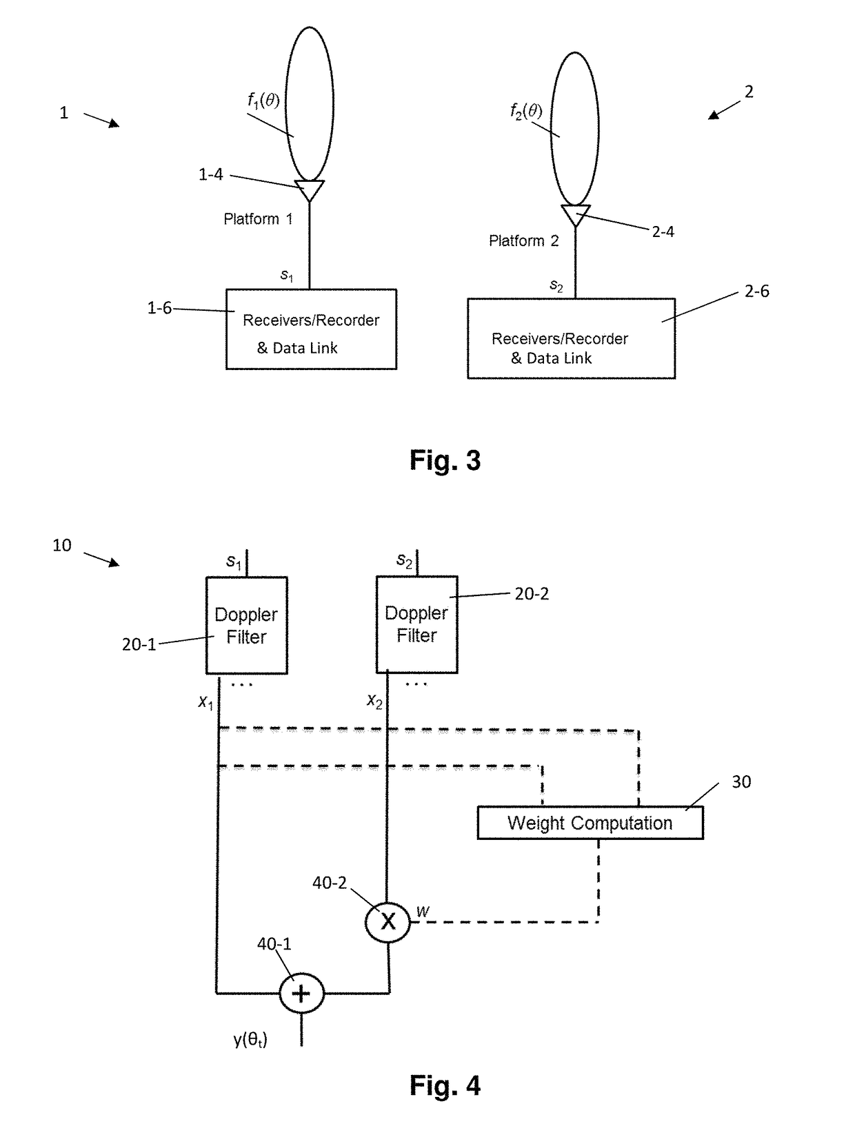
[0055]Reference will now be made in detail to the present exemplary embodiments of the invention, examples of which are illustrated in the accompanying drawings. Wherever possible, the same reference numbers will be used throughout the drawings to refer to the same or like parts. An exemplary embodiment of the system of the present invention is shown in FIG. 5, and is designated generally throughout by reference numeral 10.

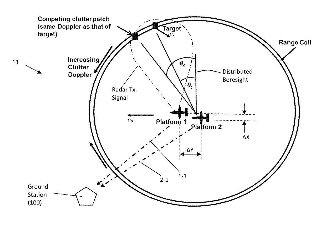
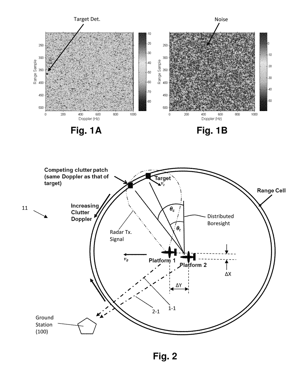
[0056]Referring to FIG. 2, a diagram illustrating the geometry of the multiplatform environment 11 is disclosed. Two aircraft (platform 1 and platform 2) are shown at the center of the drawing. As the drawing indicates, the radial velocity vo of the clutter is at a positive maximum in the direction that the platforms are traveling and negative minimum in the opposite direction. The radial absolute velocity is at a minimum amidships. The Doppler frequency of the clutter also is at a positive maximum in the direction of travel and at a negative minimum directly behi...


PUM


Abstract

The present invention is directed to a ground moving target (GMTI) radar that can detect targets, including dismounts, with very small minimum detectable velocities by combining signals from antennas on different spatially separated platforms in a main beam clutter-suppressing spatially adaptive process without requiring that the relative positions of the antenna phase centers be accurately tracked. The clutter nulling is in addition to that provided by the Doppler filters. The spatial displacement provides a narrow main beam clutter null reducing undesired target suppression. The clutter-suppressing spatially adaptive structure is used in both the sum and delta channels of the monopulse processor so that the beam distortion caused by the spatial nulling is compensated for, and the monopulse look-up process is preserved to maintain angle accuracy. Noncoherent integration is employed to recover signal to noise loss resulting from the uncertain relative locations of the platforms.

Description

GOVERNMENT RIGHTS[0001]The invention was conceived or reduced to practice under U.S. Government Contract Name Cohering Multiplatform Sensors with Disposable Transponders; Contract No. F30602-02-C-0081, Project Number DO645. The U.S. Government may have limited rights to practice the invention.BACKGROUND OF THE INVENTION[0002]1. Field of the Invention[0003]The present invention relates generally to radar processing systems, and particularly to Ground Moving Target Indicator (GMTI) radar with adaptive clutter suppression.[0004]2. Technical Background[0005]The term radar is an acronym that stands for “radio detection and ranging.” A radar system transmits radio frequency (RF) signals in a predetermined direction (i.e., a bearing) with the intention of contacting or illuminating moving objects (“contacts”). When the transmitted radar signal illuminates a contact, a return signal is reflected back toward the radar receiver. The return signal is detected if it is stronger than any noise s...

Claims


Application Information

Patent Timeline
Patent Type & Authority Patents(United States)
IPC IPC(8): G01S13/524G01S13/00G01S7/288G01S13/87
CPCG01S13/5244G01S7/288G01S13/003G01S13/87G01S7/414
Inventor SCHUMAN, HARVEY K.LI, PING G.
Owner SRC INC
Why Eureka
Try Eureka