Systems and methods for enhancing isolation of high-temperature reactor containments

a technology for containment and high-temperature reactors, which is applied in the direction of nuclear reactors, nuclear elements, greenhouse gas reduction, etc., can solve the problems of water hammer transmission, shock transmission into the reactor vessel and the containment structure, and excessive pressure, so as to limit the amount of leakage

Active Publication Date: 2017-09-26
RGT UNIV OF CALIFORNIA
View PDF5 Cites 2 Cited by
  • Summary
  • Abstract
  • Description
  • Claims
  • Application Information

AI Technical Summary

Benefits of technology

[0011]An aspect of the present disclosure is a high-temperature containment-isolation system for transferring heat from a nuclear reactor containment to a high-pressure heat exchanger using a high-temperature, low-volatility liquid coolant such as a molten salt or a liquid metal, where the coolant flow path provides liquid free surfaces a short distance from the containment penetrations for the reactor hot-leg and the cold-leg, where these liquid free surfaces have a cover gas maintained at a nearly constant pressure and thus prevent high-pressures from being transmitted into the reactor containment.
[0016]Another aspect is a containment isolation system where the cold coolant reentering the reactor containment flows upward in a standpipe and then across through a cold leg pipe into the reactor containment, and where the standpipe has a liquid free surface, and this liquid free surface has a cover gas maintained at a nearly constant pressure and thus prevents high-pressures from being transmitted into the reactor containment.
[0017]In one embodiment of the current aspect, the standpipe has a nearly neutrally buoyant plug that fills a significant fraction of the volume above the horizontal penetration into containment, that reduces the volume of coolant in the standpipe above the penetration and thus the level change in the hot well when pump speed is changed, while still limiting the maximum pressure that can be established at the cold leg penetration.
[0019]In another embodiment of the current aspect, the standpipe includes a seal loop, which prevents the cold leg from draining when the standpipe is drained.

Problems solved by technology

Because the process heat fluid or power conversion fluid (such as water, air, carbon dioxide, or helium) is normally at a higher pressure than the low-volatility liquid coolant, and may react chemically with the coolant, leaks in these process heat and power conversion heat exchangers have the potential to cause excessive pressurization, water-hammer transmission, or shock transmission into the reactor vessel and the reactor containment structure.

Method used


Image

  • Systems and methods for enhancing isolation of high-temperature reactor containments
  • Systems and methods for enhancing isolation of high-temperature reactor containments
  • Systems and methods for enhancing isolation of high-temperature reactor containments

Examples


Embodiment Construction

[0042]1. Isolation of High-Temperature Reactor Containments

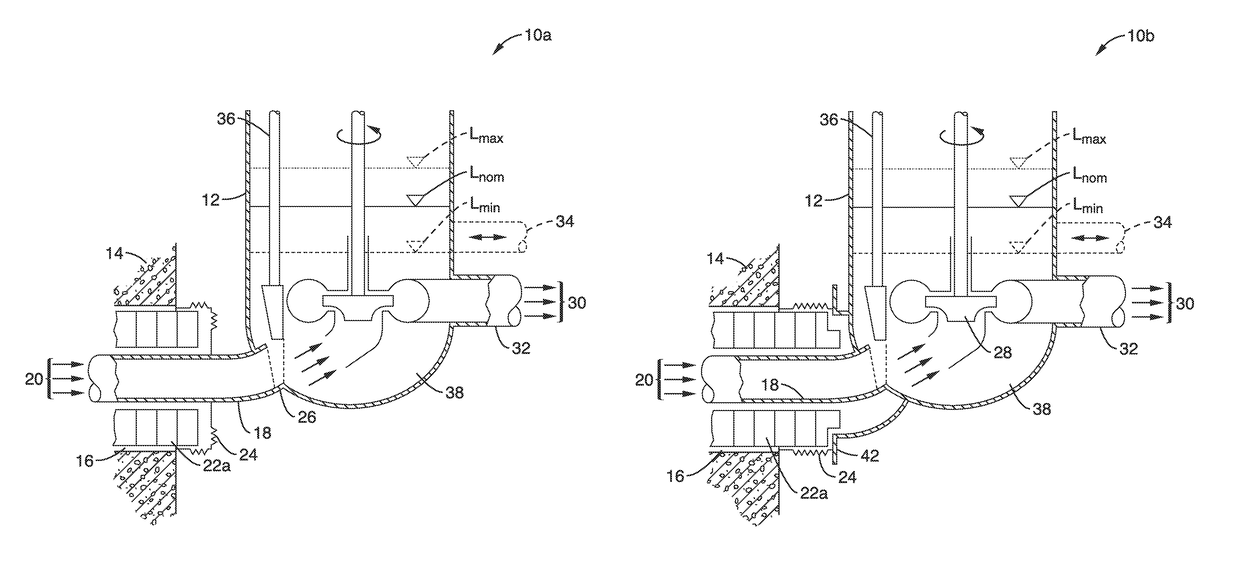
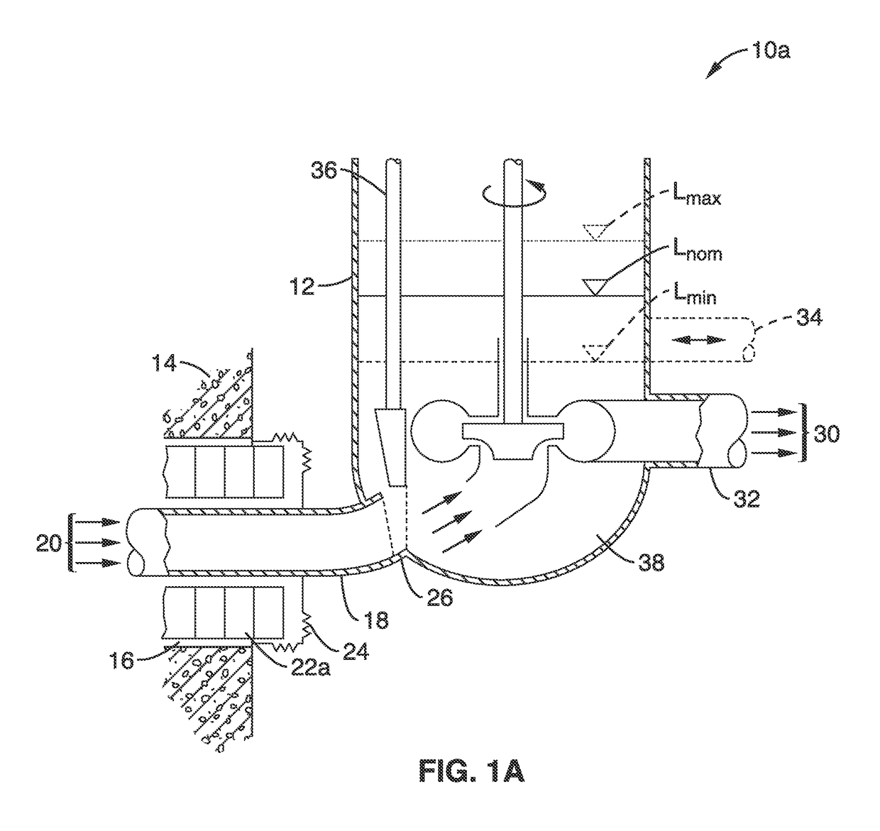
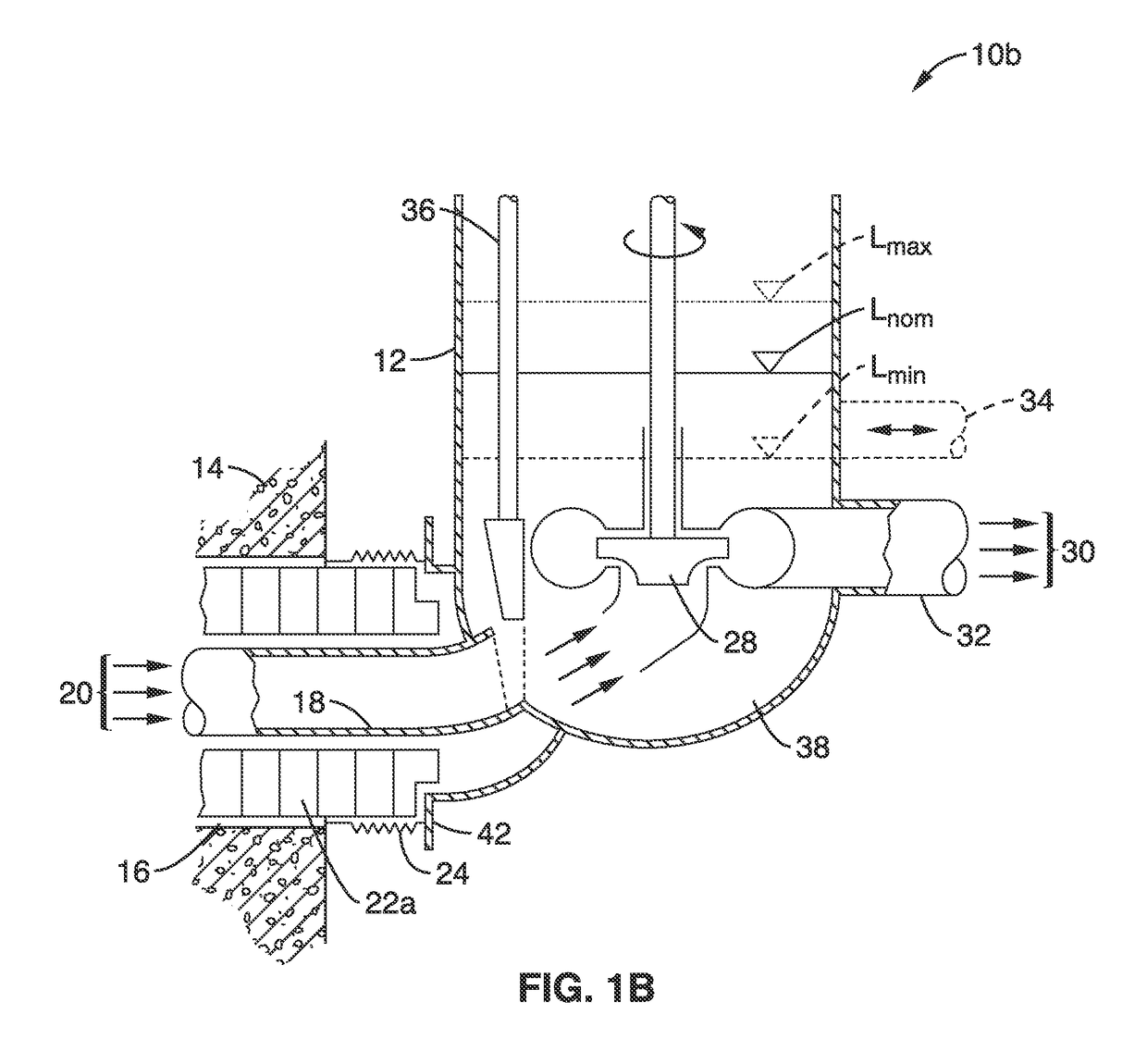
[0043]One aspect of the present disclosure is a system to prevent a leak from a high-pressure process heat or power conversion heat exchanger from causing excessive pressurization or shock loading inside the reactor containment.

[0044]In a conventional configuration to transfer heat from a nuclear reactor containment to a process heat or power conversion heat exchanger outside of the containment using a low-volatility liquid, the hot liquid exits the reactor containment structure through one or more hot-leg penetrations. The coolant flows to the high-pressure heat exchanger, and then returns via one or more cold-leg penetrations back inside the reactor containment to be heated again. The pump that circulates the coolant may be in a variety of locations around the loop, either inside or outside containment.

[0045]In the systems 10A and 10B shown in FIG. 1A and FIG. 1B, the hot coolant 20 exits the containment through a hot-leg ...


PUM


Abstract

A high-temperature containment-isolation system for transferring heat from a nuclear reactor containment to a high-pressure heat exchanger is presented. The system uses a high-temperature, low-volatility liquid coolant such as a molten salt or a liquid metal, where the coolant flow path provides liquid free surfaces a short distance from the containment penetrations for the reactor hot-leg and the cold-leg, where these liquid free surfaces have a cover gas maintained at a nearly constant pressure and thus prevent high-pressures from being transmitted into the reactor containment, and where the reactor vessel is suspended within a reactor cavity with a plurality of refractory insulator blocks disposed between an actively cooled inner cavity liner and the reactor vessel.

Description

CROSS-REFERENCE TO RELATED APPLICATIONS[0001]This application claims priority to, and the benefit of, U.S. provisional patent application Ser. No. 61 / 899,867 filed on Nov. 4, 2013, incorporated herein by reference in its entirety.STATEMENT REGARDING FEDERALLY SPONSORED RESEARCH OR DEVELOPMENT[0002]This invention was made with Government support under DE-AC07-051D14517 awarded by the United States Department of Energy (DOE). The Government has certain rights in the invention.INCORPORATION-BY-REFERENCE OF COMPUTER PROGRAM APPENDIX[0003]Not ApplicableNOTICE OF MATERIAL SUBJECT TO COPYRIGHT PROTECTION[0004]A portion of the material in this patent document is subject to copyright protection under the copyright laws of the United States and of other countries. The owner of the copyright rights has no objection to the facsimile reproduction by anyone of the patent document or the patent disclosure, as it appears in the United States Patent and Trademark Office publicly available file or re...

Claims


Application Information

Patent Timeline
Patent Type & Authority Patents(United States)
IPC IPC(8): G21C1/04G21C13/02G21C13/10G21C15/12G21C11/08G21C15/18
CPCG21C11/08G21C13/02G21C13/10G21C15/12G21C15/18Y02E30/35Y02E30/30
Inventor PETERSON, PER F.
Owner RGT UNIV OF CALIFORNIA
Why Eureka
Try Eureka