Magnetic electrical connector for patient monitors

a technology of patient monitors and electrical connectors, applied in the field of patient monitoring devices, can solve the problems of affecting the performance of patient monitors, affecting the quality of patient monitors, and unreliable connections, and achieve the effect of convenient cleaning

Active Publication Date: 2017-10-03
JPMORGAN CHASE BANK NA
View PDF1073 Cites 358 Cited by
  • Summary
  • Abstract
  • Description
  • Claims
  • Application Information

AI Technical Summary

Benefits of technology

[0011]In an embodiment, a device designer can use signal isolation to potentially establish a point of physical disconnection at the location of the insulating barrier. This may allow the designer to create an electrical connector with fewer or no exposed conductive parts. For example, in an embodiment, a transformer may have appropriate electrical characteristics to couple with the signal provided by a pair of electrodes on a subject's body. In an embodiment, the primary winding of this transformer may advantageously be a disposable electrode assembly placed near or on a patient. The cable leading to the instrument could be equipped with a secondary coil. Connection of the cable to the electrode assembly would be accomplished by bringing the coils into physical proximity, such that they are magnetically coupled, forming a transformer. It is noteworthy that this connection may have fewer or no exposed conductive parts, may be made immune or resistant to the ingress of liquids, and may be designed to be free from small cavities that would entrap biological materials, each reducing the risk of contamination and improving the efficiency and effectiveness of sterilization and signal coupling.
[0014]In an embodiment, a device designer can use a combination cerebral oximeter and EEG forehead sensor for isolation of electrical components that includes a reusable portion containing cerebral oximetry sensory components capable of detecting the cerebral oxygenation of matter inside the cerebral cavity, a disposable portion containing EEG electrodes capable of detecting electrical activity on a patient's skin, a disposable cable connecting the EEG electrodes to the reusable portion, and a signal isolation coupling connecting the disposable cable to the reusable portion. The sensor's signal isolation coupling may completely surround the signal isolation coupling to allow easy cleaning of the signal isolation coupling.

Problems solved by technology

The contact surfaces at the points of connection may be subject to contamination, corrosion, or the like, they may cause unreliable connections, or degrade the quality of the bioelectric potentials, which are usually of very low voltage levels.
The foregoing connections also may be subject to the ingress of fluids and any fluids entering a connector may degrade its performance.
The cavity or recessed mechanical structures may trap biological contaminants making cleaning and sterilization difficult.
Such difficulties may be exacerbated if the cable or wire is used on multiple subjects.
In addition to the foregoing, cables and wires leading from the patient to an instrument also present technical challenges regarding signal integrity.
The capacitance between the wires of a given cable may present an undesirable electrical loading on the electrodes.
Also, when flexed, cables may evoke triboelectric potentials, which may interfere with the signals of interest.
Moreover, cables or wire may pick up electromagnetic interference, which may also degrade the signals of interest.
However, a long cable may create significant capacitance to ground, as well as to adjacent cables, at least in part defeating that isolation.
The foregoing may lead to signal degradation, often in the form or reduced common-mode rejection.
This drawback may be exacerbated where electrosurgical and related RF devices are employed in a subject.

Method used


Image

  • Magnetic electrical connector for patient monitors
  • Magnetic electrical connector for patient monitors
  • Magnetic electrical connector for patient monitors

Examples


Embodiment Construction

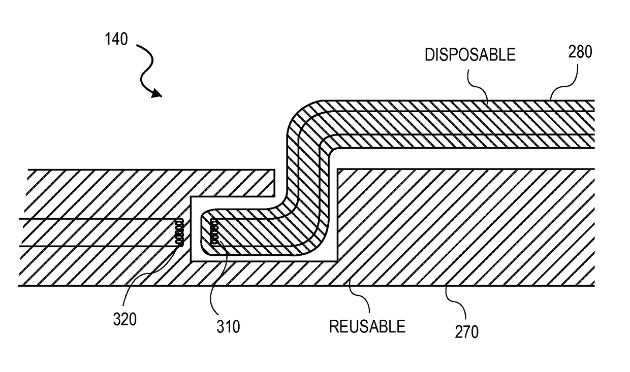
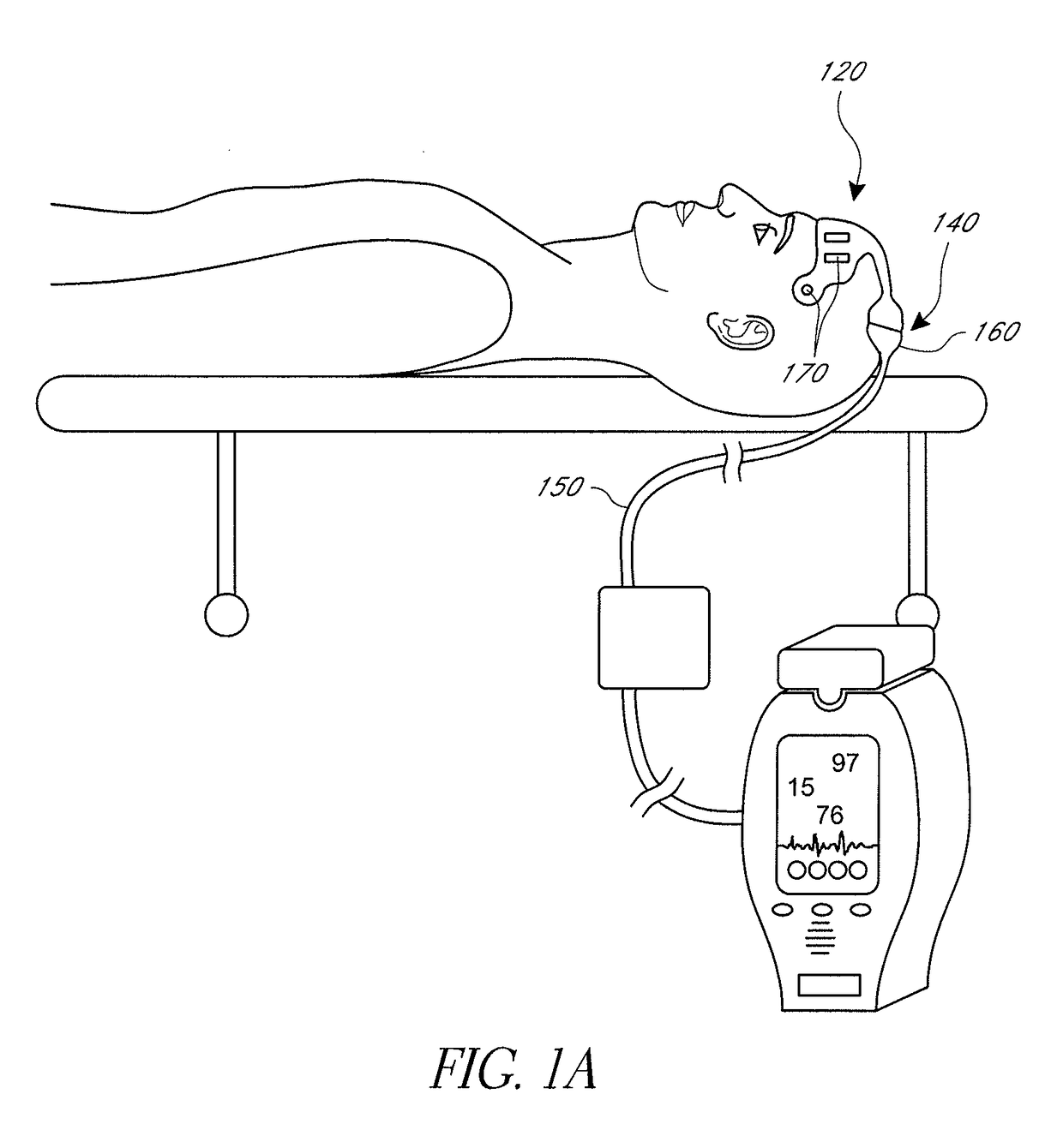
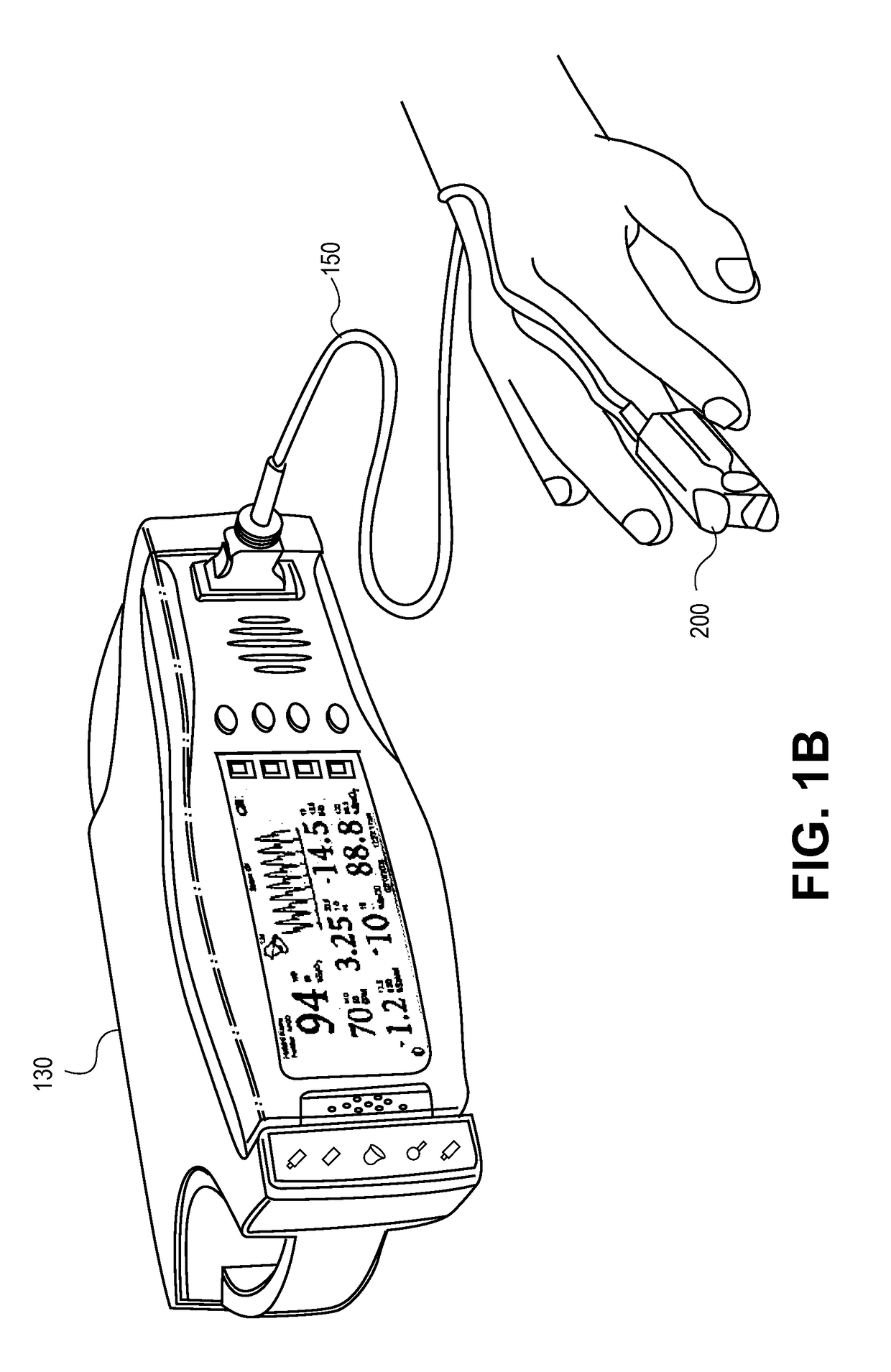
[0024]The present disclosure is generally related to signal couplings. In an embodiment, in order to provide an electrical coupling with fewer exposed conductors, and which reduces the ingress of liquids and entrapment of biological materials, an isolation connection is provided utilizing inductance and a physical gap between the conductors of the coupling. In an embodiment, a variety of medical devices could utilize a signal isolation connection between, among other places a sensor or other component interacting with a patient's body and the main instrument. For example, a device designer could implement a signal isolation component between a pulse oximeter and pulse oximetry sensor, an electroencephalogram “EEG” and the EEG electrodes, an electrocardiograph “ECG” and the ECG electrodes, acoustic throat sensors and a respiratory monitor, a temperature probe and a thermometer, and other medical devices with elements that come into close contact with a patient's body.

[0025]FIGS. 1A-1...


PUM


Abstract

The present disclosure relates to an electrical connector for providing signal isolation between various components of a physiological monitoring system. In an embodiment, the electrical connector is placed between a sensor and associated monitoring system and includes a physical barrier and inductive components.

Description

PRIORITY CLAIM[0001]This application claims the benefit of priority under 35 U.S.C. §119(e) of the following U.S. Provisional Patent Application No. 61 / 387,426, titled “Magnetic Electrical Connector For Patient Monitors,” filed on Sep. 28, 2010, and incorporates that application by reference herein in its entirety.REFERENCE TO RELATED APPLICATIONS[0002]This application is related to U.S. Provisional Patent Application No. 61 / 387,457, titled “Depth of Consciousness Monitor Including Oximeter,” filed on Sep. 28, 2010, and incorporates that application by reference herein in its entirety.FIELD OF THE DISCLOSURE[0003]The present disclosure relates to the field of patient monitoring devices. More specifically, the disclosure relates to electrical connectors for patient monitors adapted to measure blood analyses through optical noninvasive sensors.BACKGROUND OF THE DISCLOSURE[0004]Electric potentials evoked within a living subject are often sensed with electrodes or assemblies of multiple...

Claims


Application Information

Patent Timeline
Patent Type & Authority Patents(United States)
IPC IPC(8): A61B5/00A61B5/1455A61B5/0476
CPCA61B5/14551A61B5/0476A61B5/14553A61B5/6814A61B2562/227A61B2562/245A61B5/369
Inventor AL-ALI, AMMARKINAST, ERIC KARL
Owner JPMORGAN CHASE BANK NA
Why Eureka
Try Eureka