Magnet configurations for magnetic levitation of wind turbines and other apparatus

a technology of wind turbines and magnet configurations, which is applied in the direction of machines/engines, renewable energy generation, greenhouse gas reduction, etc., can solve the problems of fraught problems, energy loss during the process, and frequent and costly repairs, and achieve the effect of stabilizing the operation of the apparatus and enhancing the stability of operation

Active Publication Date: 2017-10-24
HOVER ENERGY LLC
View PDF10 Cites 3 Cited by
  • Summary
  • Abstract
  • Description
  • Claims
  • Application Information

AI Technical Summary

Benefits of technology

[0007]The present invention is directed to techniques, systems and methods to increase the efficiency of a wind turbine or like apparatus by reducing the friction occurring between the component parts of a wind turbine through a new magnet configuration. A wind turbine includes a turbine rotor, a turbine support, one or more blades coupled to the turbine rotor, where the one or more blades are configured to move the turbine rotor relative to the turbine support. Efficiency is improved by locating one or more magnet sets between the turbine support and the turbine rotor, creating a space therebetween. The rotational movement of the turbine rotor is essentially frictionless and minimal energy is expended during rotation of the turbine blades. The energy output produced by the turbine rotor is transmitted to one or more generators that are configured to generate electric power from the rotational movement of the turbine rotor.
[0008]In the instant invention, a set of dipolar magnets is coupled to a turbine rotor and a turbine support in a novel configuration. The set of dipolar magnets is used to create a space between the turbine rotor and turbine support, thereby reducing the friction force between the turbine rotor and the turbine support.
[0010]In this way, the entire apparatus employing the improved magnet configuration of the present invention controls the erratic magnetic fluxes and has enhanced stability of operation thereby. Additionally, axially-disposed alignment magnets may also be deployed to further stabilize the operation of the apparatus.

Problems solved by technology

As is set forth in physics, particularly Betz' Law, during the operation of the horizontal axis and vertical axis wind turbines, energy is lost during the process as the mechanical pieces of the windmill lose energy to frictional forces.
Further, the friction between the moving parts in existing systems creates maintenance problems, which require frequent and costly repairs, primarily due to the need for system downtime for such work.
Yet, the use of magnets for levitation, well known in the train industry, is fraught with problems.
A chief problem in the usage of magnetic levitation is the control of the fluctuating magnetic fields, i.e., stability.
This problem is further manifest in vertical axis wind turbine systems that attempt to levitate components to reduce friction, employing a single magnet around a center axis pole.
These prior art systems, however, have not been able to stabilize the magnetic fluxes and also fail to eliminate friction, leaving the entire apparatus at risk.

Method used


Image

  • Magnet configurations for magnetic levitation of wind turbines and other apparatus
  • Magnet configurations for magnetic levitation of wind turbines and other apparatus
  • Magnet configurations for magnetic levitation of wind turbines and other apparatus

Examples


Embodiment Construction

[0022]The following detailed description is presented to enable any person skilled in the art to make and use the invention. For purposes of explanation, specific nomenclature is set forth to provide a thorough understanding of the present invention. However, it will be apparent to one skilled in the art that these specific details are not required to practice the invention. Descriptions of specific applications are provided only as representative examples. Various modifications to the preferred embodiments will be readily apparent to one skilled in the art, and the general principles defined herein may be applied to other embodiments and applications without departing from the scope of the invention. The present invention is not intended to be limited to the embodiments shown, but is to be accorded the widest possible scope consistent with the principles and features disclosed herein.

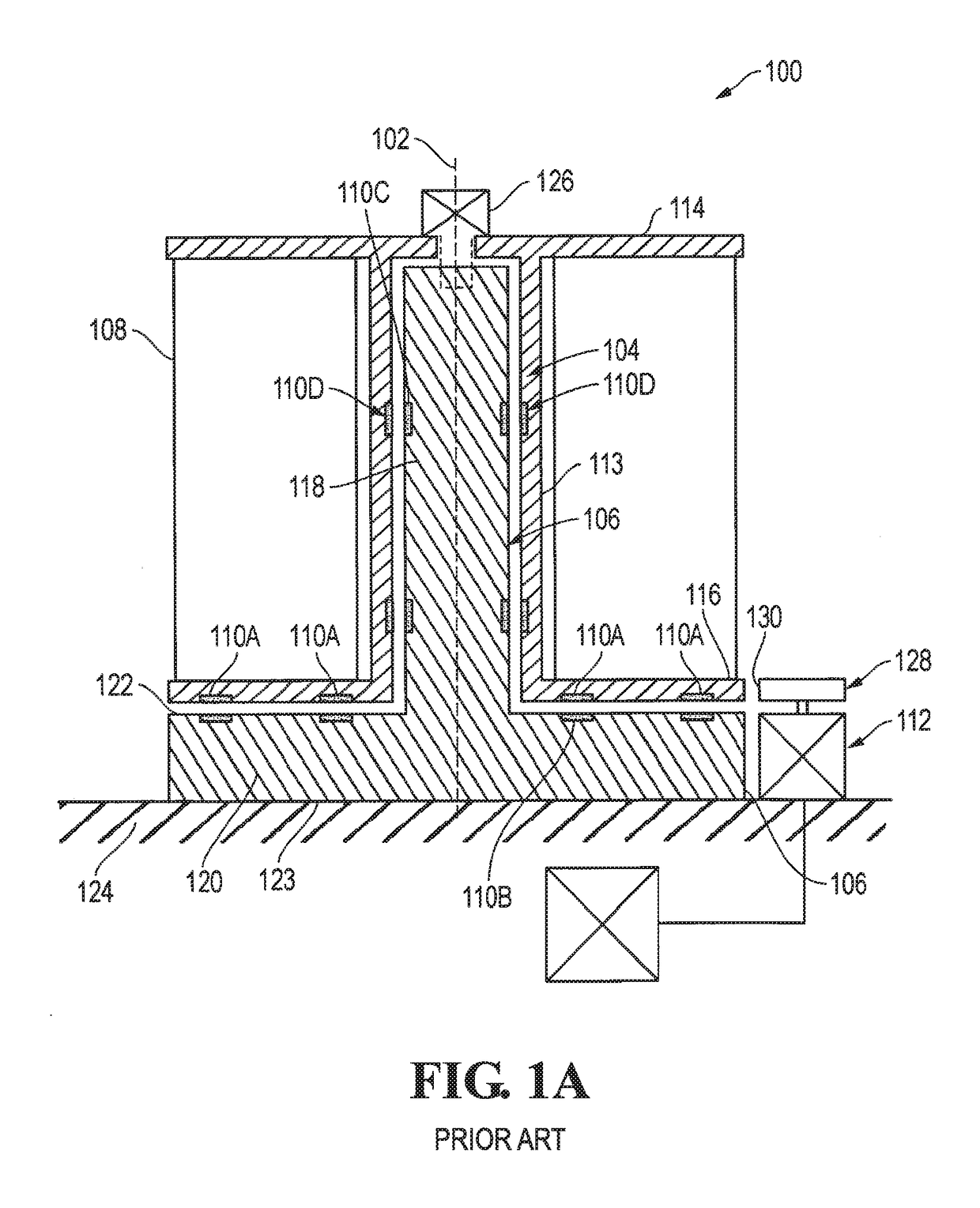
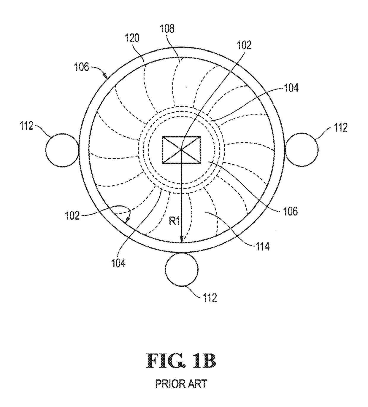
[0023]With reference now to FIG. 1 of the DRAWINGS, there is illustrated therein a schematic cross ...


PUM

PropertyMeasurementUnit
diameteraaaaaaaaaa
diameteraaaaaaaaaa
outer diameteraaaaaaaaaa

Abstract

A wind turbine having one or more magnets for reducing friction between the turbine support and a turbine rotor. The reduction of friction between the turbine rotor and the turbine support allows for an increase in energy production and scale of the wind turbines. The magnet configuration employs a ring of cylindrically-shaped magnets at the bottom and opposed by a corresponding number of generally rectangular-shaped magnets. Bearing magnets are also employed for axial stabilization.

Description

RELATED PATENT APPLICATION[0001]The present application is a continuation from U.S. nonprovisional of U.S. patent application Ser. No. 14 / 322,750, filed Jul. 2, 2014, now U.S. Pat. No. 9,388,795, and also claims benefit from Provisional Patent Application Ser. No. 61 / 843,030, filed Jul. 4, 2013, the disclosures of which are incorporated herein by reference.BACKGROUND OF THE INVENTION[0002]The capture of wind power and the translation of that power into energy have been a long-time human endeavor. From ancient windmills to the giant wind farms of today, the efficient capture and harnessing of this renewable energy is of paramount importance to modern economies. With the growing need for cleaner energies, the importance of advances in cleaner alternative energy production is manifest.[0003]Wind turbines harness the kinetic energy of the wind and convert it into mechanical or electric power. Traditional wind turbines have a horizontal spinning axis that allowed blades of the wind turbi...

Claims


Application Information

Patent Timeline
Patent Type & Authority Patents(United States)
IPC IPC(8): F03D9/00F03D9/25F03D3/00F03D80/70
CPCF03D80/70F03D9/002F03D9/25F03D3/005F05B2220/706F05B2240/211F05B2280/4007F05B2260/404F05B2240/511F05B2240/51Y02E10/74F03D15/10F03D3/0454
Inventor CHOI, CHEONG S.JENKINS, ANTHONY MICHAEL
Owner HOVER ENERGY LLC
Why Eureka
Try Eureka