
Touch display panel structure, method for forming the same, and touch display device

a technology of touch display panel and method, which is applied in the direction of instruments, computing, electric digital data processing, etc., can solve the problems of high manufacturing cost and complicated manufacturing process, and achieve the effects of reducing cost, improving manufacturing efficiency, and simplifying process steps

Active Publication Date: 2017-10-24
SHANGHAI TIANMA MICRO ELECTRONICS CO LTD +1
View PDF12 Cites 0 Cited by
  • Summary
  • Abstract
  • Description
  • Claims
  • Application Information

AI Technical Summary

Benefits of technology

[0005]A touch display panel structure, a method for forming the touch display panel structure, and a touch display device are provided according to the present disclosure, to simplify the manufacturing process of a display device.
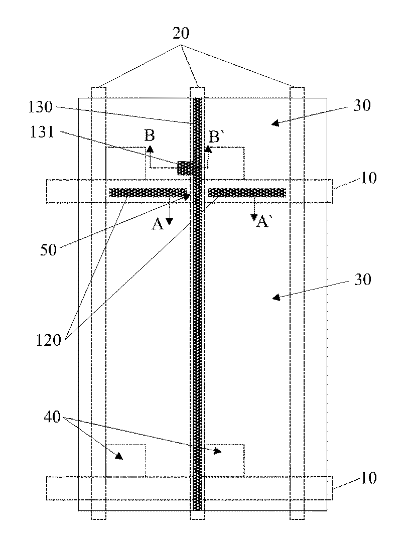
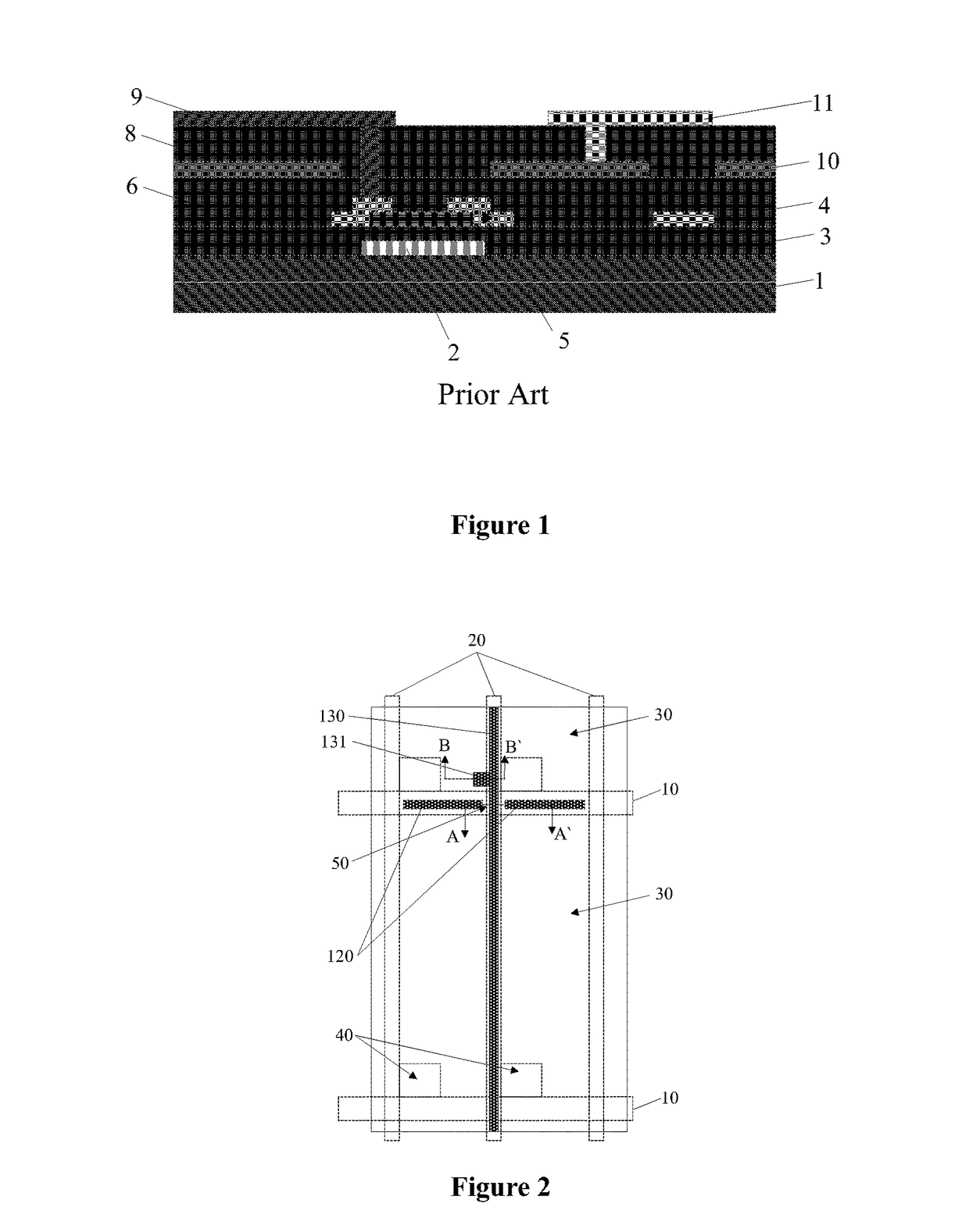
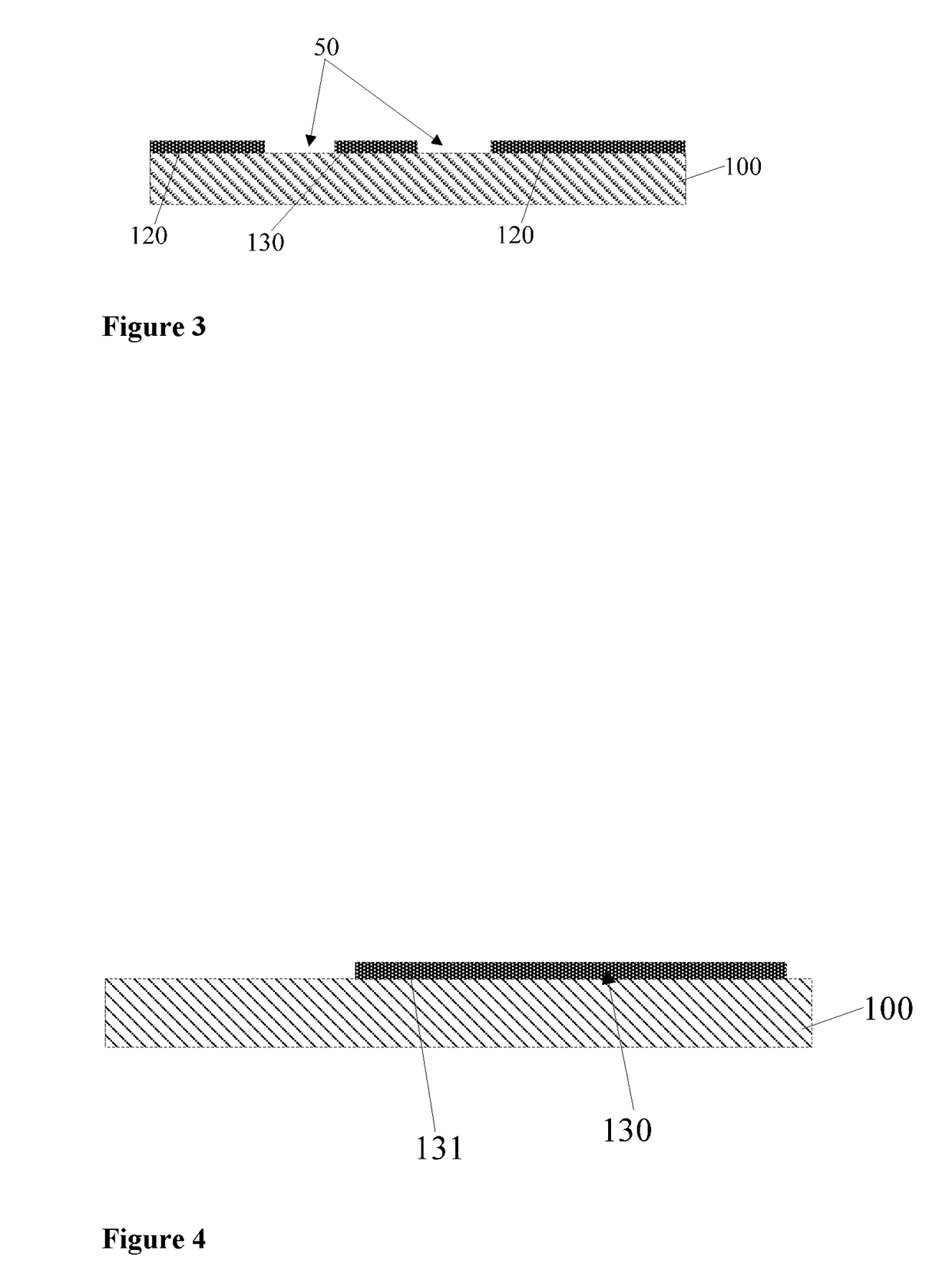
[0020]Compared with the conventional art, the advantageous effect of the technical solution of the present disclosure includes: the scan lines extending in the first direction are disposed in the same layer as the touch electrode lines on the substrate, wherein each scan line includes a plurality of scan line segments electronically connected to each other through the first interconnection structures, and the touch electrode line is connected to the common electrode via at least the first via hole. In this way, the scan lines and the touch electrode lines can be formed in one step during the manufacture process, rather than in the conventional art where the touch electrode lines are formed in an additional step, thereby simplifying the process step and saving the mask.
[0021]In addition, the data lines are formed right above the touch electrode lines, and the projections of the data lines in a direction perpendicular to the substrate overlap the touch electrode lines. In this way, the data lines help shield the touch electrode lines against interference signals, that is, the data lines help reduce the crosstalk suffered by the touch electrode lines.
[0023]As described above, the touch display device may simplify the manufacturing process and reduce the cost.
[0035]Compared with the fact in the conventional art that the touch electrode lines are formed in an additional step, the scan lines and the touch electrode lines can be formed in one step according to the method for forming a touch display panel structure in the present disclosure, thus achieving the effects of simplifying the process step, reducing the cost and improving the manufacturing efficiency. In addition, the data lines are formed right above the touch electrode lines, and projections of the data lines in a direction perpendicular to the substrate overlap the touch electrode lines. In this way, the data lines help shield the touch electrode lines against interference signals, that is, the data lines help reduce the crosstalk suffered by the touch electrode lines.

Problems solved by technology

Hence, the entire manufacture process is complicated, and cost for the manufacture is high.

Method used


Image

  • Touch display panel structure, method for forming the same, and touch display device
  • Touch display panel structure, method for forming the same, and touch display device
  • Touch display panel structure, method for forming the same, and touch display device

Examples


Embodiment Construction

[0056]For clarity of the above object, features and advantages of the present disclosure, particular embodiments of the present disclosure are illustrated below in detail in conjunction with the accompanying drawings.

[0057]As described in the background, in the conventional art, touch electrode lines for connecting a common electrode are formed in an additional step to achieve a touch control function, which leads to the results that the process step and cost are increased and the manufacturing efficiency is reduced.

[0058]In view of the above-described problems, it is provided a method for forming an array substrate according to an embodiment of the present disclosure. Reference is made to FIG. 2 to FIG. 18, which are schematic structural diagrams of a touch display panel structure in various steps of the method for forming the touch display panel structure according to an embodiment of the present disclosure.

[0059]Reference is made to FIG. 2 to FIG. 4. FIG. 2 is a schematic top vie...


PUM

PropertyMeasurementUnit
conductiveaaaaaaaaaa
sizeaaaaaaaaaa
weightaaaaaaaaaa

Abstract

A touch display panel structure, a method for forming the touch display panel structure, and a touch display device are provided. The touch display panel structure includes: a substrate, scan lines each including a plurality of scan line segments, touch electrode lines each disposed at an interval between adjacent scan line segments; a first dielectric layer and data lines; a second dielectric layer and a first interconnection structure; a first via hole through the first dielectric layer and the second dielectric layer; a third dielectric layer a common electrode layer; a second via hole through the first dielectric layer and the second dielectric layer; and a plurality of third via holes through the third dielectric layer, wherein each touch electrode is connected to a touch electrode line via the second via hole and the third via hole.

Description

CROSS REFERENCE TO RELATED APPLICATIONS[0001]This application claims priority to Chinese Patent Application No. 201510152692.6, titled “TOUCH DISPLAY PANEL STRUCTURE, METHOD FOR FORMING THE SAME, AND TOUCH DISPLAY DEVICE”, filed with the Chinese State Intellectual Property Office on Apr. 1, 2015, which is incorporated by reference in its entirety herein.BACKGROUND OF THE DISCLOSURE[0002]Display devices are widely used in various fields due to advantages such as a small size, a light weight and low radiation. Some display devices in conventional art have touch functions. Generally, a common electrode in the display device is divided into multiple blocks, and common electrodes in each block share a touch electrode. In the conventional art, a lead is disposed for each touch electrode to enable each touch electrode to output signals.[0003]Referring to FIG. 1, an array substrate in a Mid-Com structure in the conventional art is taken as an example. The array substrate in the Mid-Com stru...

Claims


Application Information

Patent Timeline
Patent Type & Authority Patents(United States)
IPC IPC(8): G06F3/041G06F3/044G02F1/1362G02F1/1333
CPCG06F3/0412G02F1/136286G06F3/044G06F2203/04111G02F1/13338G06F2203/04103G02F1/134309G06F3/041G06F3/0443G06F3/0446G06F3/04164
Inventor DING, HONGDU, LINGXIAOLU, FENG
Owner SHANGHAI TIANMA MICRO ELECTRONICS CO LTD
Learn More