
CPAP systems

a technology of pap system and air delivery tube, which is applied in the direction of valves, respirators, mechanical devices, etc., can solve the problems of only being able to use tubing, users are apprehensive, and the size of the air delivery conduit is not considered, and achieves the effect of convenient and quick connection, small size, and compact packaging

Active Publication Date: 2017-10-31
RESMED LTD
View PDF32 Cites 18 Cited by
  • Summary
  • Abstract
  • Description
  • Claims
  • Application Information

AI Technical Summary

Benefits of technology

The solution results in a more compact, comfortable, and efficient CPAP system that can deliver a broader range of pressures with reduced heat loss and power consumption, improving patient compliance and comfort by minimizing impedance and pressure swings.

Problems solved by technology

However, there has been very little attention paid to the size of the air delivery conduit, which acts as the interface between the patient interface and the flow generator.
However, the tubing may only be used for pressures up to 15 cm H2O.
As CPAP therapy is generally conducted in the home, this medical tubing can make users apprehensive in adopting the therapy because the medical tubing can look out of place amongst the environment commonly found in a user's bedroom.
In addition, the tubing may be bulky and not easily packed up or organized to preserve the look of a bedroom.
Furthermore, the sound caused by the medical tubing as it brushes against linen and the added physical interference as far as drag to the patient interface can cause the user some discomfort.
There is no current standard ISO tubing size other than 22 mm outer diameter available for use with CPAP systems across the full flow generator pressure range.
Also, current tubing can communicate airflow but are restrictive in communicating electrical signals.
The problems with using tubing with a smaller bore include the high impedance in the tube to provide the desired pressure at the patient interface.
Presently, some flow generators are not able to supply sufficient power for the full pressure range required.
Also, there are large pressure swings due to the flow generator not being able to respond quickly enough to changes in pressure.

Method used


Image

  • CPAP systems
  • CPAP systems
  • CPAP systems

Examples


Embodiment Construction

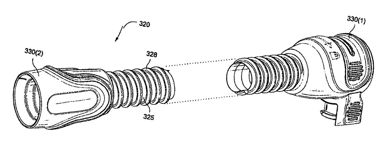
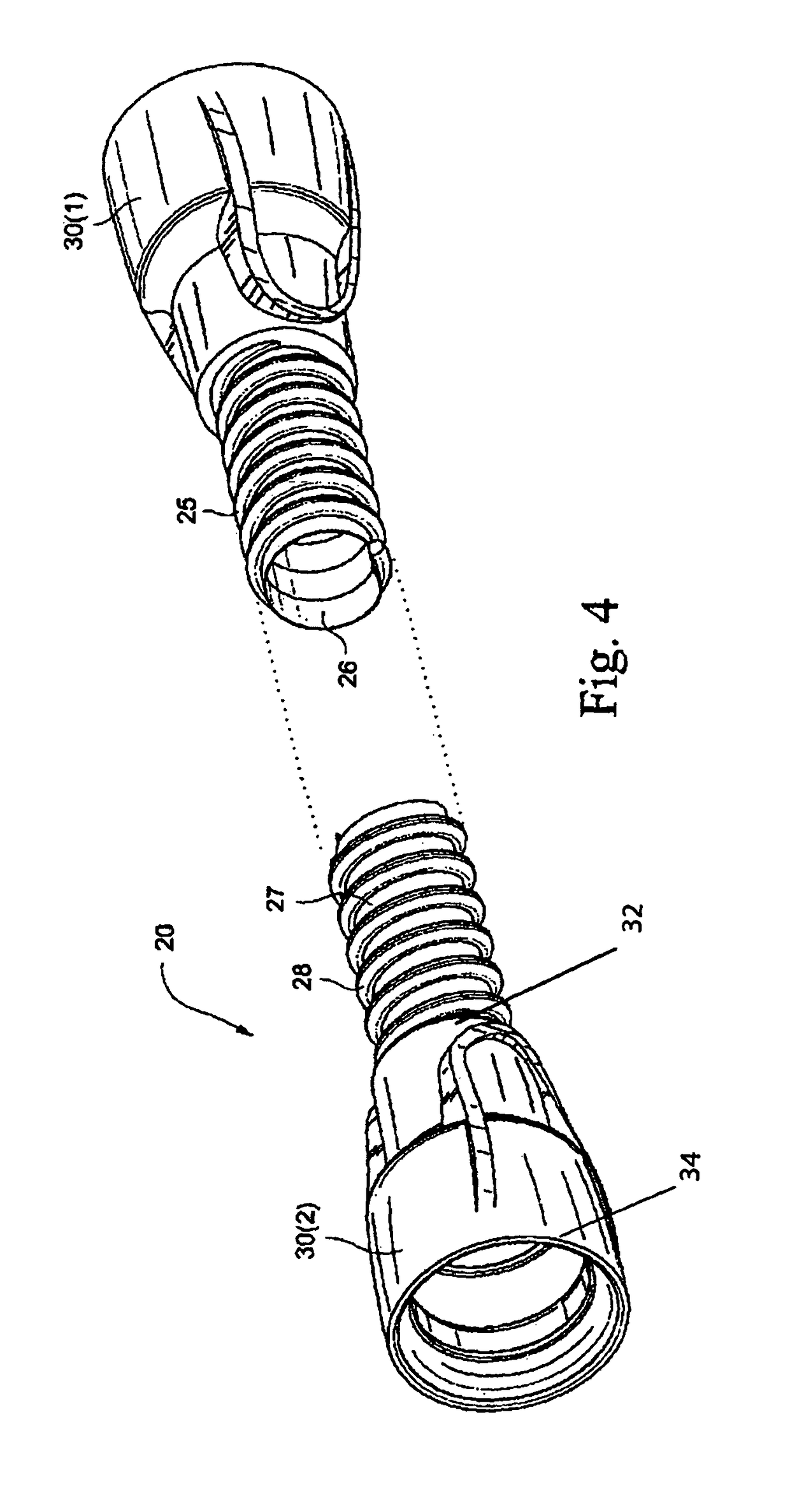
[0029]A CPAP system generally includes a flow generator, an air delivery conduit, and a patient interface. In use, the flow generator generates a supply of pressurized air that is delivered to the patient via an air delivery conduit that includes one end coupled to the outlet of the flow generator and an opposite end coupled to the patient interface. The patient interface comfortably engages the patient's face and provides a seal. The patient interface may have any suitable configuration as is known in the art, e.g., full-face mask, nasal mask, oro-nasal mask, mouth mask, nasal prongs, etc. Also, any suitable headgear arrangement may be utilized to comfortably support the patient interface in a desired position on the patient's face.

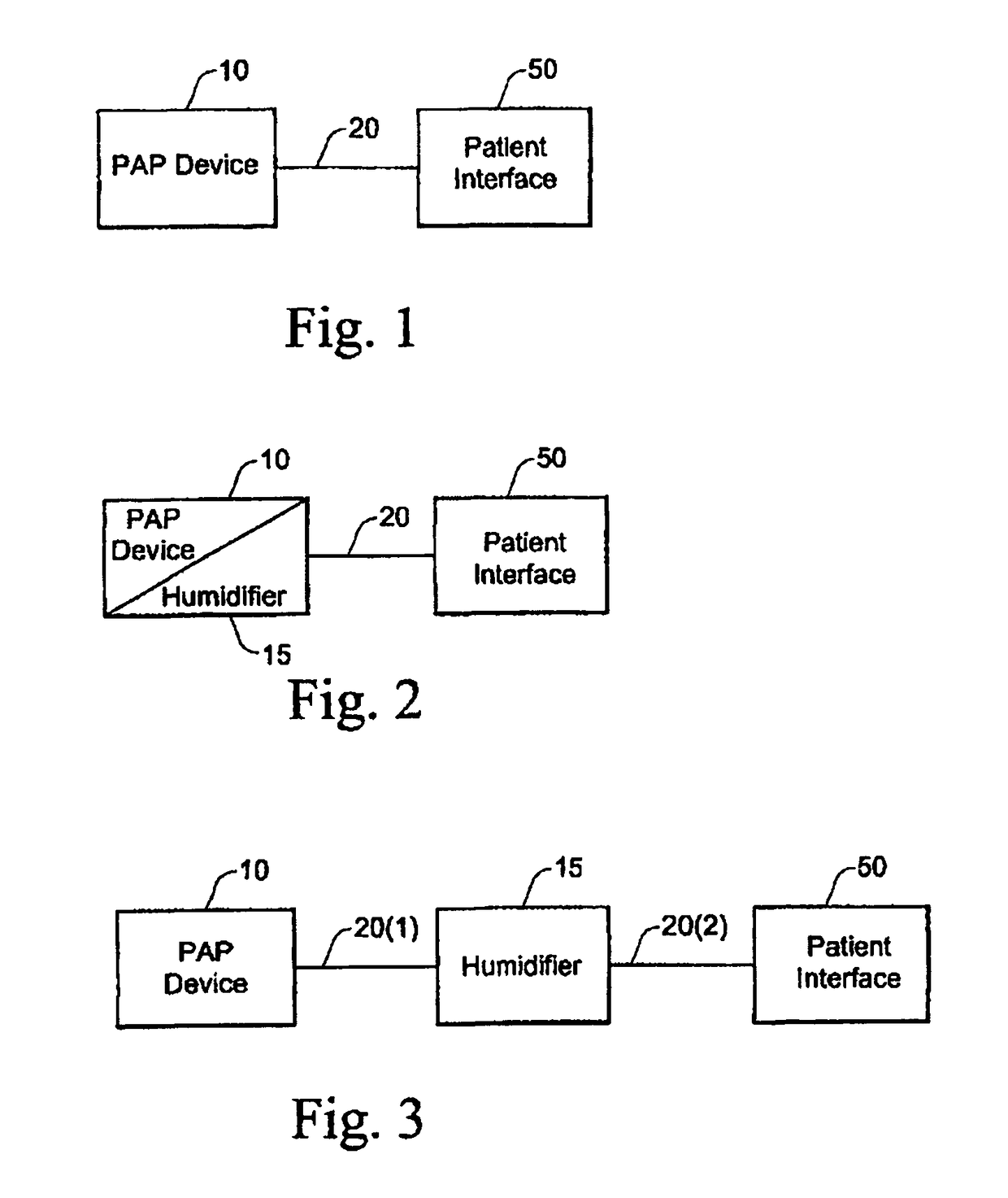
[0030]As schematically shown in FIG. 1, a PAP system (e.g., CPAP system) generally includes a PAP device 10, an air delivery conduit 20 (also referred to as a tube or tubing), and a patient interface 50. In use, the PAP device 10 generates a supply of pr...


PUM


Abstract

A CPAP system includes a flow generator (10), a patient interface (50), an air delivery conduit (20) that interconnects the flow generator and the patient interface, wherein the air delivery conduit has an internal diameter of less than 19 mm. Preferably the air delivery conduit has an internal diameter of between about 10 mm and about 18 mm. The CPAP system may also include a controller for compensating for pressure swings and / or increased impedance within the system. Preferably the blower includes a low inertia blower.

Description

CROSS-REFERENCE TO RELATED APPLICATIONS[0001]The present application is a national phase entry under 35 U.S.C. §371 of International Application No. PCT / AU2010 / 001462 filed Nov. 3, 2010, published in English, which claims priority from Australian Provisional Application No. 2009905945 filed Dec. 7, 2009 and Australian Provisional Application No. 2009905363 filed Nov. 3, 2009, all of which are incorporated herein by reference.FIELD OF THE INVENTION[0002]The present invention relates to a PAP system and air delivery tubing that delivers breathable gas to a patient.BACKGROUND OF THE INVENTION[0003]Colin Sullivan was the first to invent the use of nasal Continuous Positive Airway Pressure (CPAP) to treat Obstructive Sleep Apnea (OSA), e.g., see U.S. Pat. No. 4,944,310. The treatment generally provides a supply of air or breathable gas from a blower to a patient via an air delivery conduit and a patient interface, such as a full-face or nasal mask or nasal prongs. The air or breathable g...

Claims


Application Information

Patent Timeline
Patent Type & Authority Patents(United States)
IPC IPC(8): A61M16/00A61M16/08A61M16/10A61M16/16
CPCA61M16/0051A61M16/0069A61M16/0875A61M16/1075A61M16/1095A61M2205/3653A61M2016/0021A61M2016/0027A61M2016/0039A61M2205/3365A61M2205/3368A61M16/16A61M16/026A61M2205/6018
Inventor VIRR, ALEXANDERTARAKCI, CEMOATES, JOHN DAVIDKENYON, BARTON JOHNCUTCLIFFE, GRAHAM STEPHENROW, NATHAN JOHN
Owner RESMED LTD
Learn More