Temporary production system and separator with vapor recovery function

a production system and separator technology, applied in the field of separation, can solve the problems of limited equipment space, increased labor intensity, and increased labor intensity, and achieve the effect of facilitating the temporary production of hydrocarbons and enhancing oil recovery

Active Publication Date: 2017-10-31
PROS
View PDF8 Cites 9 Cited by
  • Summary
  • Abstract
  • Description
  • Claims
  • Application Information

AI Technical Summary

Benefits of technology

[0006]The presently disclosed temporary hydrocarbon well production system and associated fluid separator provides a solution to the problem identified above. The disclosed system facilitates the temporary production of hydrocarbons following the drilling, completion, work-over and / or stimulation of a hydrocarbon well (including stimulation wells, such as wells for the injection of water, steam, CO2, or wells utilized for other enhanced oil recovery methods). An embodiment of the temporary hydrocarbon well production system comprises a production line connected to a hydrocarbon well. The production line flows into a sand separator, which has a fluid outlet connected to a choke manifold and a solids outlet connected to a sand dump line. A closed separator receives flow through two separate lines from the choke manifold and from the sand dump line, which respectively flow into independent diffusing structures in the closed separator. These diffusing structures are capable of receiving high velocity solids-laden fluid. Any gas, vapors, volatile organic compounds, etc. which are entrained within either of the separate flow lines are captured within the closed vessel and discharged through a vapor discharge line attached to a vapor recovery unit for either further processing or incineration through a flare. A liquid dump line discharges liquids from the closed separator to at least one closed tank.

Problems solved by technology

Because of the large array of equipment which is typically moved in and out of the location, there may be little space available at the well location.
This problem is further exacerbated on offshore platforms, drilling islands, piers, and other remote well locations where available space for equipment can be extremely limited.
The availability of space at the well location can be further complicated when the well is stimulated by hydraulic fracturing and / or acidizing.
These pieces of equipment are typically large and can consume a significant amount of the available footprint at the location.
The fluids produced from a well which has been placed on production following drilling, work-over, and / or stimulation, such as by hydraulic fracturing, may contain a number of components which are difficult to manage on a crowded well location, such as a high concentration of solids, high gas production rates, and returned stimulation fluids, such as spent acid or frac fluids.
The escape of these VOCs into the atmosphere is undesirable because of the escape of the pollutants.
However, no practical and satisfactory solution for temporarily producing the solids and fluids from newly completed and stimulated wells has been developed.

Method used


Image

  • Temporary production system and separator with vapor recovery function
  • Temporary production system and separator with vapor recovery function
  • Temporary production system and separator with vapor recovery function

Examples


Embodiment Construction

[0025]The fluids produced by a newly drilled well, a re-drilled well, or a well which has been worked-over by perforating and / or stimulation may comprise fluids which are native to the hydrocarbon reservoir, such as oil, gas, condensates, water, and / or hydrocarbon-water emulsions. Entrained within the produced fluids may be solids such as formation sand and paraffin. However, particularly at start-up, in addition to native fluids and solids, the produced fluids may also comprise fluids and solids which were introduced into the well during the drilling and completion processes, with such fluids including drilling mud, completion fluids, spent acids solutions, and fracturing fluids, including solid propping materials introduced with those fluids such as sand, bauxite, etc.

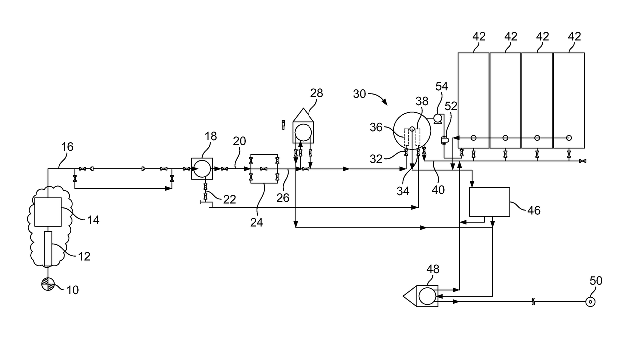
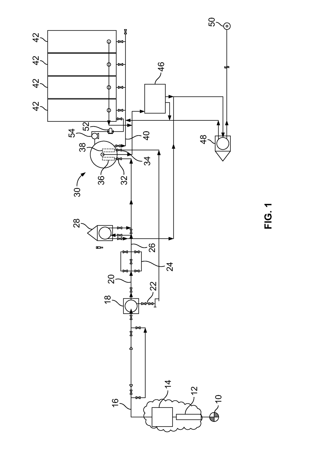
[0026]Referring now to the figures, FIG. 1 schematically shows a temporary hydrocarbon well production system. In this system, flow originates from hydrocarbon well 10 which may flow through a data header 12, which i...


PUM

PropertyMeasurementUnit
diameteraaaaaaaaaa
diameteraaaaaaaaaa
diameteraaaaaaaaaa

Abstract

A temporary hydrocarbon well production system receives flow from a hydrocarbon well through a production line connected to the well. The production line flows into a sand separator, which has a fluid outlet connected to a choke manifold and a solids outlet connected to a sand dump line. A transportable and vertical closed separator receives flow through two separate lines from the choke manifold and from the sand dump line, which respectively flow into independent diffusing structures in the closed separator. Gas, vapors, volatile organic compounds, etc. are captured within the closed vessel and are discharged through a vapor discharge line attached to a vapor recovery unit for either further processing or incineration through a flare. A liquid dump line discharges liquids from the closed separator to at least one closed tank.

Description

BACKGROUND OF THE INVENTION[0001]This application relates to separators utilized for separating fluids produced from hydrocarbon wells, specifically to separators utilized for separating fluids produced from a hydrocarbon well during the flowback of drilling and stimulation fluids which are produced during the initial testing of a producing zone or following completion, re-completion, workover, or stimulation. Because this type of production frequently occurs with a drilling rig or work-over rig still on the well location, the well location is typically crowded with the rig and associated components, tanks, pumps, logging units, cementing units, pump trucks, drill string components, casing components, support vehicles, and other equipment utilized in the drilling or work-over operation. Because of the large array of equipment which is typically moved in and out of the location, there may be little space available at the well location. This problem is further exacerbated on offshore ...

Claims


Application Information

Patent Timeline
Patent Type & Authority Patents(United States)
IPC IPC(8): E21B43/34
CPCE21B43/34B01D21/2405B01D21/245B01D21/2494B01D2221/04E21B43/35
Inventor LEAL, JAMES E
Owner PROS
Why Eureka
Try Eureka