
Method for denoising time-of-flight range images

a time-of-flight range and image denoising technology, applied in image enhancement, image analysis, instruments, etc., can solve the problems of noise from tof cameras, measurement bias, and noise from tof camera hardware limitation, so as to reduce scene independent noise, reduce scene dependent noise, and reduce scene independent noise

Active Publication Date: 2017-10-31
MITSUBISHI ELECTRIC RES LAB INC
View PDF1 Cites 43 Cited by
  • Summary
  • Abstract
  • Description
  • Claims
  • Application Information

AI Technical Summary

Benefits of technology

The patent describes a method to reduce noise in a calibration process using a planar checkerboard and a ToF camera. The method also involves capturing a dataset with various multi-path distortion patterns using a ToF camera and a high-precision structured light sensor to train two feedforward neural networks. The result is a filtering algorithm that reduces the scene-dependent noise in the range image. Overall, the method improves the accuracy and reliability of the calibration process.

Problems solved by technology

However, compared to 3D sensors based on laser or structured light, ToF cameras are noisier.
The scene independent noise comes from the limitation in manufacturing the ToF camera hardware including the infrared emitter (non-ideal sinusoidal modulation), the sensor (CMOS gate difference for each pixel), and the optics.
The limitation results in measurement bias, which depends on the pixel location, the measured range value, and the measured amplitude value.
The scene dependent noise is the result of the multipath behavior of the flash light.
It leads to the distortion of:1) range over-shooting due to the superposition of the reflection lights from neighboring structure; and2) range smoothing due to the superposition of the reflection signals from foreground and background regions.
However, the global calibration model fails to model the pixel location dependent bias in the ToF range image, which limits an achievable accuracy.
Simulation-based methods require good initial range estimates and are generally slow.
Multiple modulation frequencies-based methods require special hardware and are inapplicable to off-the-shelf ToF cameras where only a single modulation frequency is available.
Those methods effectively remove random noises but cannot correct measurement biases and retrieve fine structure since those methods do not model the ToF image property.
However, those methods are not directly applicable to denoising a ToF range image since the ToF range image has different characteristics than a conventional optical image.

Method used


Image

  • Method for denoising time-of-flight range images
  • Method for denoising time-of-flight range images
  • Method for denoising time-of-flight range images

Examples


Embodiment Construction

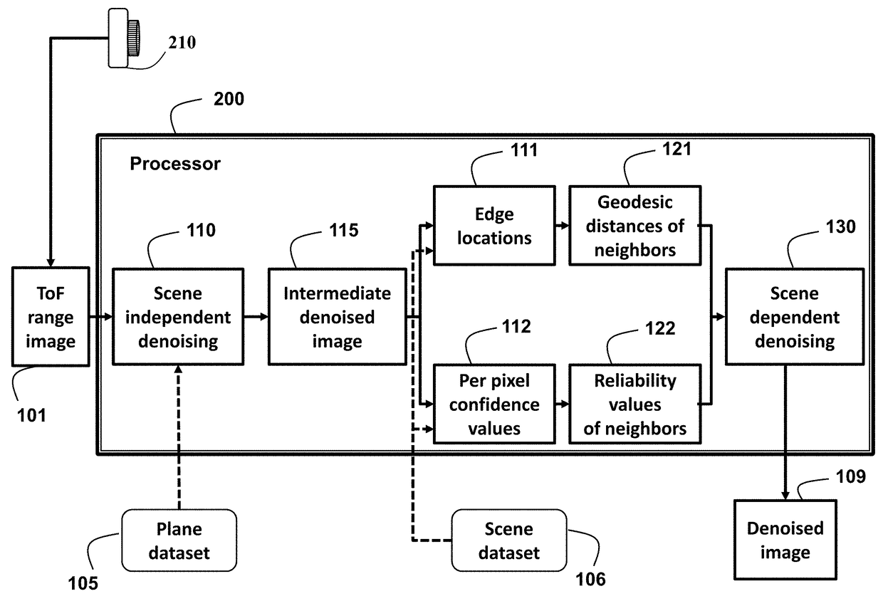
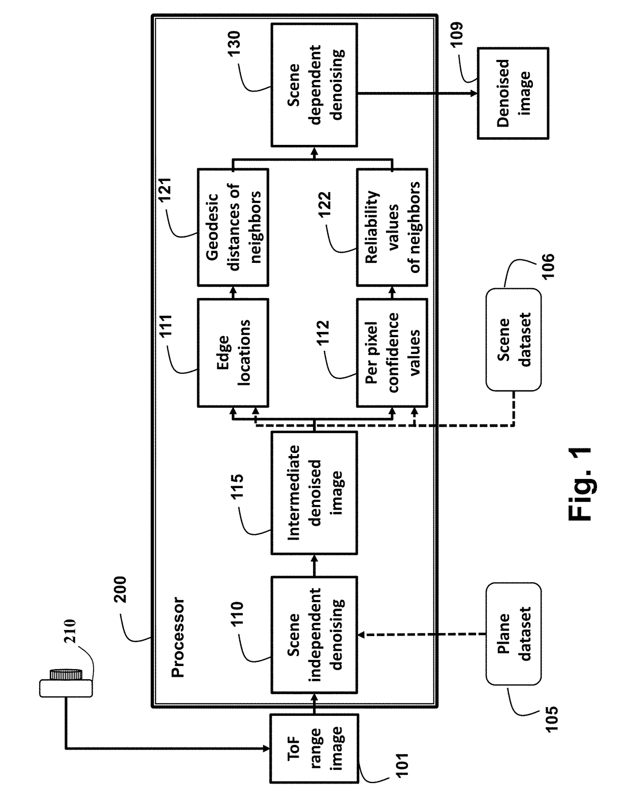
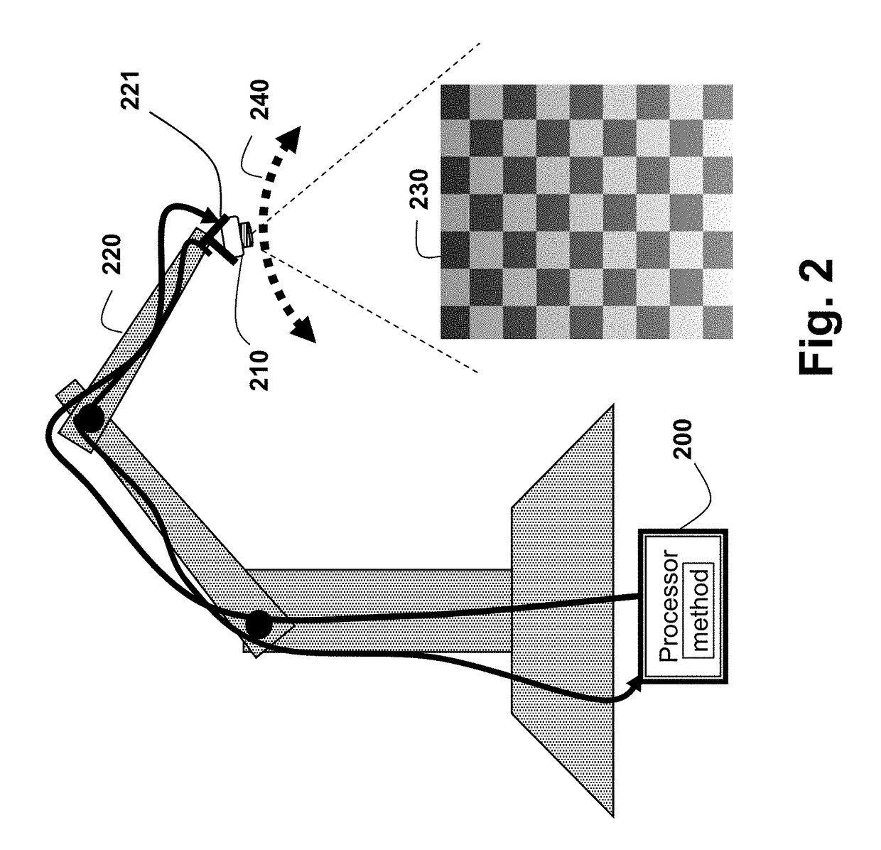
[0016]As shown in FIG. 1, the embodiments of our invention provide a method for denoising a time-of-flight (ToF) range image 101 to produce a denoised image 109. The method can be can be performed in a processor 200 connected to memory and input / output interfaces by buses as known in the art, see FIG. 2.

[0017]Herein, we use range (a distance between a center of the camera and a 3D point in a scene) instead of depth (a Z coordinate of the 3D point in the camera coordinate system), because the range directly corresponds to a phase shift in the signals used by the ToF range camera. The amplitude of the range signal corresponds to a confidence value or reliability of the range measurement.

[0018]The method uses a data-driven approach for denoising the ToF range image by reducing scene independent noise based on a plane dataset 105 and scene dependent noise using a scene dataset 106, as described below. The datasets are used during training to learn various models, neural networks, and pa...


PUM


Abstract

A method for denoising a range image acquired by a time-of-flight (ToF) camera by first determining locations of edges, and a confidence value of each pixel, and based on the locations of the edges, determining geodesic distances of neighboring pixels. Based on the confidence values, reliabilities of the neighboring pixels are determined and scene dependent noise is reduced using a filter.

Description

FIELD OF THE INVENTION[0001]This invention relates generally to image processing, and more particularly to reducing noise in time-of-flight (ToF) range images.BACKGROUND OF THE INVENTION[0002]Time-of-flight (ToF) cameras capture scene depth by measuring a phase delay of a modulated signal emitted by an infrared LED flash towards the scene in the space. ToF cameras have become a popular choice for many computer vision applications including human-computer interaction, 3D reconstruction, and object detection. ToF cameras have the advantages of low cost, high speed, and compact form. However, compared to 3D sensors based on laser or structured light, ToF cameras are noisier. Noise in the ToF camera can be classified into two major categories: scene independent noise and scene dependent noise.[0003]The scene independent noise comes from the limitation in manufacturing the ToF camera hardware including the infrared emitter (non-ideal sinusoidal modulation), the sensor (CMOS gate differen...

Claims


Application Information

Patent Timeline
Patent Type & Authority Patents(United States)
IPC IPC(8): G06K9/66G06T7/60G06K9/62G06T7/521G06T5/00G06K9/46G06K9/52G06T7/13
CPCG06K9/66G06K9/52G06K9/6215G06T5/00G06T5/002G06T7/13G06T7/521G06T7/60G06K9/4604G06T2207/20192G06T2207/10028G06T2207/20004G06T2207/20024G06T2207/20081G06T2207/20084G06T2207/20182G06T5/70G06T5/60G06F18/22
Inventor LIU, MING-YUTAGUCHI, YUICHISON, KILHO
Owner MITSUBISHI ELECTRIC RES LAB INC
Learn More