
Illumination control system

a control system and a technology for gps, applied in the direction of photometry using reference value, electric lighting sources, electric light sources, etc., can solve the problems of inability to use gps function indoors, people may easily get lost in shopping malls and lose their ways,

Active Publication Date: 2017-10-31
INT MOBILE IOT
View PDF17 Cites 24 Cited by
  • Summary
  • Abstract
  • Description
  • Claims
  • Application Information

AI Technical Summary

Benefits of technology

The patent describes a system that uses sensors to determine the brightness and presence of people in a room and adjusts the lighting to make the room comfortable and energy-efficient. It also includes a feature that wakes up people gently by focusing light on their face to prevent alarms from going off too early in the morning. Overall, the system helps save energy and reduce carbon dioxide emissions by making buildings more efficient.

Problems solved by technology

1. Occupancy sensor: a function of the occupancy sensor is to automatically turn the lights on when a person enters a room and turn the lights off when the person leaves. The occupancy sensor comes handy for one who carries items with both hands when entering a room such as a laundromat, a kitchen, or a workplace.
2. Vacancy sensor: a function of the vacancy sensor is to turn the lights off when the person leave a room, but the person needs to manually turn the lights on when entering the room. The vacancy sensor is an ideal choice for the bedroom, as the lights would not be automatically turned on when one's partner walks in during sleep. The vacancy sensor is a preferable choice if the household includes a pet.
3. Daylight sensor: the daylight sensor dims or turns lights off when sufficient daylight is provided in a room. The daylight sensor is an ideal choice for a room with many windows, such as a family room or a sun room. This type of sensor fully uses the available daylight, reduces dependency on electrical light, and helps lower electricity costs.
4. Passive infrared sensor (PIR): the passive infrared sensor (PIR) detects temperature changes so as to determine whether someone enters a room and whether lights should be turned on. The PIR is suitable for being installed in a small and closed environment so as to detect obvious movements of a person, because the design thereof is for detecting primary movements. The strength thereof is to easily detect a person walking in or out of a space. However, a weakness thereof is that the PIR automatically turns the lights off when the PIR determines the person is not active, such that the sudden darkness causes inconvenience because the person needs to be active in order to keep the lights on.
5. Ultrasonic sensor: whether an object is moving or not in a room may be detected by reflection generated by transmitting ultrasound to the object and detecting acoustic frequency offsets between transmissions and reflections. The ultrasonic sensor is adept at detecting slight movements, such as typing, and does not need a surrounding with a bare sight vision.
6. Wireless sensor: the wireless sensor does not require new wirings and is easily installed and programmed. Each of the batteries in the wireless sensor lasts ten years, and the wireless sensor may be easily relocated for reconfigurations. Additional sensors may be installed at any time so as to expand a coverage area of the sensor in the room. These sensors transmit radio frequency (RF) signals to a dimmer and a switch, and the RF signals instruct them what to do. These sensors operate in a low frequency band (434 MHz) so as to avoid interference of other wireless devices. Wired sensors directly connected to a light control device are suitable for new buildings and battery changes are not required.
However, since current illumination systems do not detect locations, identities, and emotions of indoor users, there is much room for improving the intelligence of the current illumination systems.
In the modern society, buildings such as residential buildings, shopping malls or skyscrapers are becoming colossal, and people may easily get lost in a shopping mall and lose their ways.
Although many mobile communication devices have a built-in global positioning system (GPS), the GPS function cannot be used indoors.
Therefore, the system is costly and inconvenient.

Method used


Image

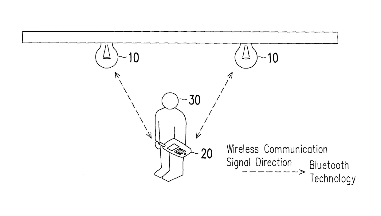
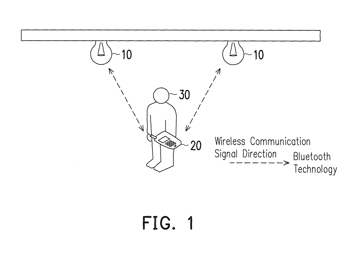
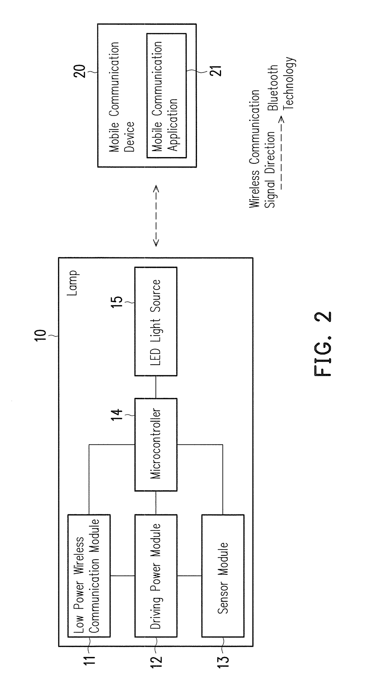
  • Illumination control system
  • Illumination control system
  • Illumination control system

Examples


embodiment 1

[0069]FIG. 11 is a sample figure illustrating an indoor lighting configuration of the illumination control system of the invention. First, a command may be directly transmitted from a personal cellular phone to the lamp 10 in a bedroom, such as the lamp 10 in the bedroom which may be configured for having a function of a vacancy sensor. The lamp is not turned on automatically when people come in and out during your sleep. A method for turning on the lamp 10 is through a cellular phone or a bracelet, or through a cellular phone or a bracelet with a voice command. Sufficient lighting is maintained in children room so children would not be afraid. A function of occupancy sensor may be set for an entrance where no one stays to turn the lamp on when presence of the user is detected and to turn the lamp off when the user leaves. The lamp having a function of a daylight sensor may be set up for places with many windows, such as a living room, a balcony and a yard, and light adjusting will ...

embodiment 2

or Remotely Turning Lights on and Off

[0083]FIG. 14 illustrates one embodiment of the bracelet. A sliding shaft 153 having two sections of switches is ON. The primary purpose thereof is to start movements and recording after activating power source of the bracelet or being connected to a cellular phone. If the red LED lamp 154 flashes slowly, it indicates that charging is needed because power of the bracelet is dying. When the sliding shaft 153 having two sections of switches is OFF, power will be shut down. A red button 151 is deemed as an emergency button. If seniors or children at home, patients in emergency rooms of hospitals, or inpatients have emergency issues or are in need of getting help, they may press this button asking for help by sending requests through proximate a BT4.0 / WIFI router, a BT4.0 / PLC router or BT4.0 / GATEWAY to Clouds. At this time, an LED lamp 154 flashes quickly. If the Cloud receives the requests, it sends rescuers and transmits a signal showing the receip...

embodiment 4

able of Dimming by Remote Control

[0092]Regardless of day time or night time, if the most appropriate illumination is required, a preferable way is to use the illumination sensor to provide illuminance corresponding to the current environment and compensate to provide enough illumination. The illumination sensor may be electrically connected to a Bluetooth control panel, but a position thereof where the illumination sensor senses is based on the capability of detecting ambient illumination. The illumination sensor may be arranged in the bracelet for directly detecting whether sufficient illumination around a wearer is provided. If the illumination sensor is not required, a way to tell whether illumination is sufficient or not is to adopt daytime lighting and nighttime lighting, which primarily distinguish daytime from nighttime through sunrise or sunset time.

[0093]Functions of manually-control buttons are the same as those of a remote control. As shown in FIG. 16, a primary function ...


PUM


Abstract

An illumination control system provides wireless data transmission with a lamp through a mobile communication device. The lamp has a built-in wireless communication module and a microcontroller. The microcontroller stores a location of the lamp with latitude-longitude values and height values. Accordingly, a user may use the mobile communication device to read the latitude-longitude values and height values of the lamps to achieve an indoor positioning function by calculating a positioning information of the user through indoor positioning algorithms, and thereby enable illumination control through the mobile communication device according to the positioning information.

Description

CROSS-REFERENCE TO RELATED APPLICATION[0001]This application claims the priority benefit of Taiwan application serial no. 102110230, filed on Mar. 22, 2013. The entirety of the above-mentioned patent application is hereby incorporated by reference herein and made a part of this specification.BACKGROUND[0002]Field of the Invention[0003]The invention relates to an illumination control system, and more particularly, the invention relates to an illumination control system that senses a status of a user through a sensor and accurately obtains latitude-longitudes and indoor floor heights of the user through a user positioning function, and controls illumination of light sources based on the positioning data.[0004]Description of Related Art[0005]In a society with aging population and declining birthrate, the importance of adopting an intelligent life and home care system has increased, and illumination has become indispensable in daily life. Thus, intelligent illumination systems have been...

Claims


Application Information

Patent Timeline
Patent Type & Authority Patents(United States)
IPC IPC(8): G01J1/20H05B37/02H05B44/00
CPCH05B37/0272H05B47/19H05B47/1965
Inventor HUANG, JUNG-TANG
Owner INT MOBILE IOT
Learn More