Lighting system, track and lighting module therefore
a technology of lighting system and track, applied in the field of lighting system, can solve the problems of visual disturbance, difficult to attach the lamp to the track or move the module, and attract undesirable attention, and achieve the effects of small size, less design freedom, and more efficient and cheaper
- Summary
- Abstract
- Description
- Claims
- Application Information
AI Technical Summary
Benefits of technology
Problems solved by technology
Method used
Image
Examples
first embodiment
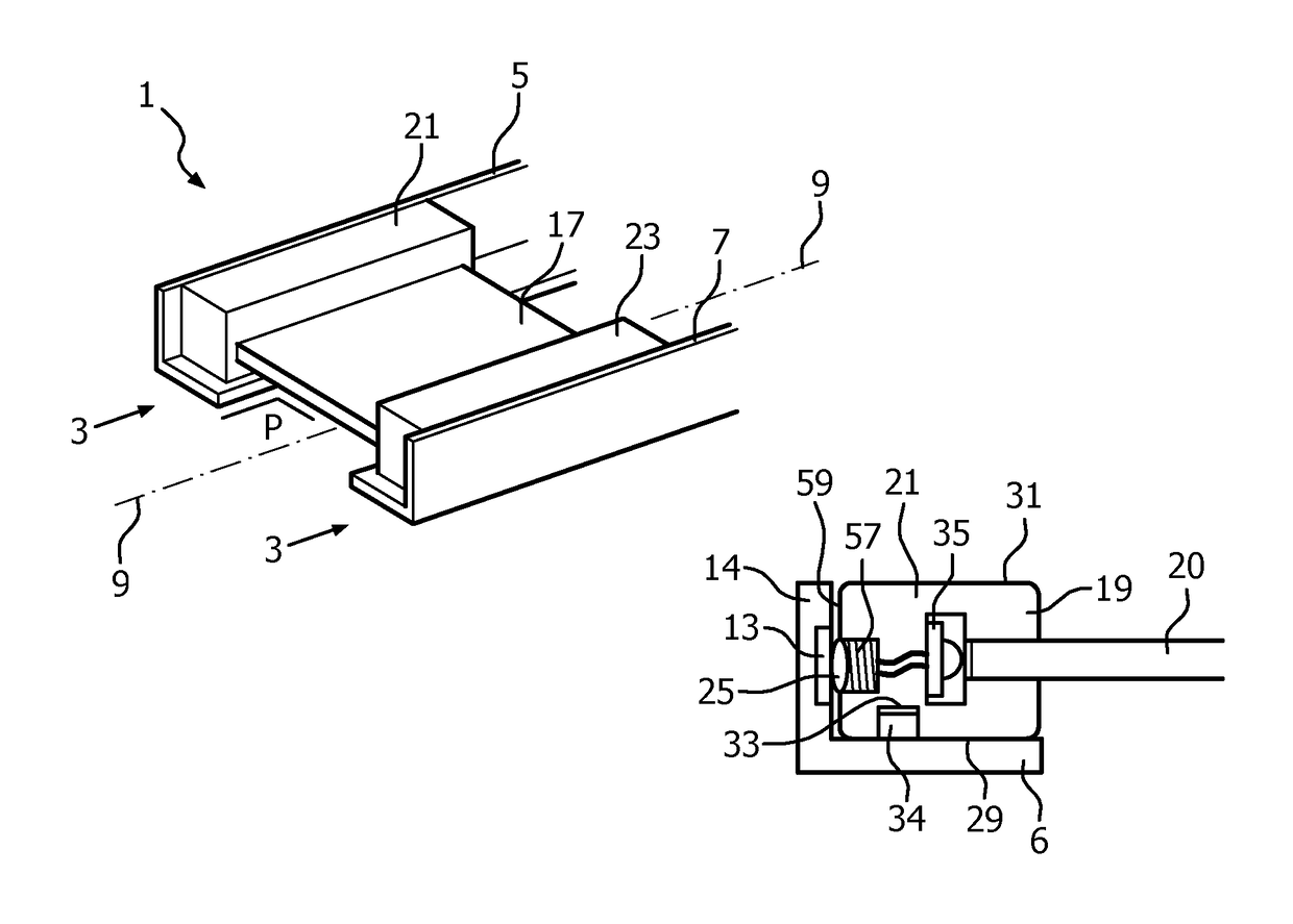
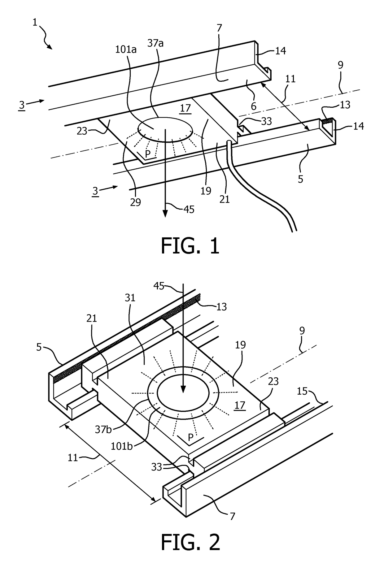
[0147]FIGS. 1 and 2 schematically show respectively a perspective bottom view and a top view of the lighting system 1 according to the invention. The lighting system comprises a track 3 comprising a first 5 and a second rail 7 extending mutually parallel along an axis or length axis 9. The first and second rail are spaced apart by an opening 11 lying in a plane P as defined by the parallel extending first and second rail. If the first and second rail are slightly curved, i.e. that the first and second rail together bend slightly out of a flat plane upwards or downwards, then the plane P is considered locally and follows the curvature of the first and second rail. The first and second rails have a U-shaped profile in cross-section. Both the first and second rail comprise a respective conductive strip 13,15 which are isolated from each other and are provided at a respective rail wall 14 extending from a carrier side 6 of the rail normal to plane P along the axis. Alternatively, the co...
second embodiment
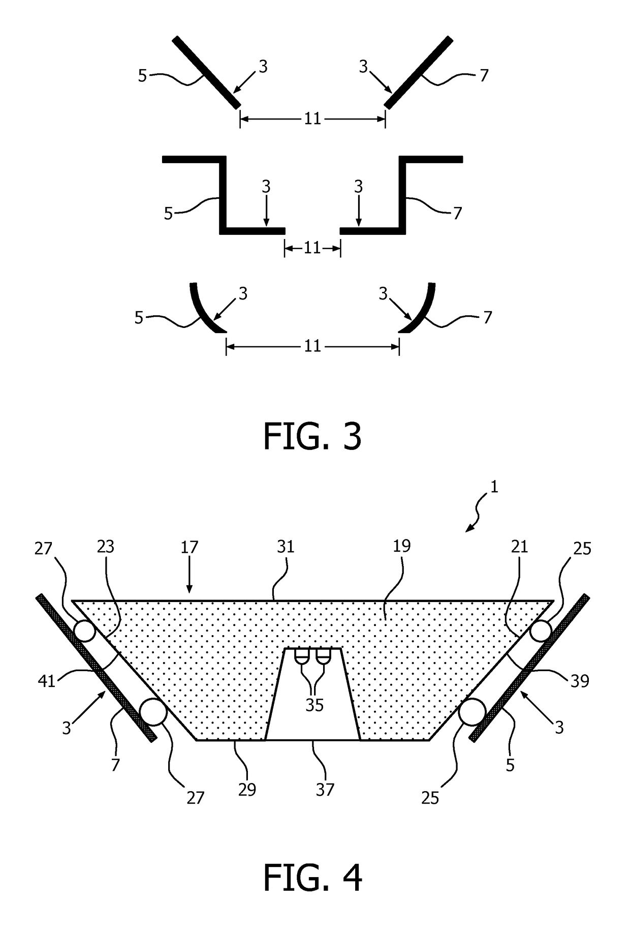
[0149]FIG. 4 shows a cross section of the lighting system 1 according to the invention. In this embodiment the lighting module 17 comprises a light source 35, in the figure two LEDs, in the base, which base 19 on its first side 29 has a light emission window 37 through which, during operation, light is issued to below the track 3. The lighting module at its first 21 and second end 23 has resilient contacts 25, 27 provided at a first 39 and second side face 41 extending from the first side 29 towards the second side 31 of the base and rests with these resilient contacts on the rails 5,7 of the wedge-shaped track 3.
third embodiment
[0150]FIG. 5 shows cross sections of the lighting system1 according to the invention with the lighting module 17 being in a horizontal position and in a tilted position with respect to the plane P and opening 11. The side faces 39,41 of the lighting module are curved and are each provided with a metallic electric conducting coating 25,27 which act as electric contacts 25,27 of the module and which electrically connect to respective electric conductive strips 13,15 provided on the rails 5,7. The frictional contact between lighting module and rails enable the lighting module to stay in a somewhat tilted orientation (for aiming a light beam 43 issued at a tilting angle α with the direction of gravity through the light emission window 37). However, when the tilting angle becomes too large, i.e. that an end 21,23 of the lighting module becomes positioned too close to the bottom part of one of the rails, it will automatically slide back into a smaller, safer titling angle.
[0151]FIG. 6 sho...
PUM
 Abstract
Description
Claims
Application Information
 - R&D
- Intellectual Property
- Life Sciences
- Materials
- Tech Scout
- Unparalleled Data Quality
- Higher Quality Content
- 60% Fewer Hallucinations
Browse by: Latest US Patents, China's latest patents, Technical Efficacy Thesaurus, Application Domain, Technology Topic, Popular Technical Reports.
© 2025 PatSnap. All rights reserved.Legal|Privacy policy|Modern Slavery Act Transparency Statement|Sitemap|About US| Contact US: help@patsnap.com


