Polyisocyanurate based cement for wellbore fluid loss prevention

a technology of polyisocyanurate and cement, which is applied in the direction of drilling composition, chemistry apparatus and processes, etc., can solve the problem of unworkable control of the reactivity of two-component polyurethane based cemen

Active Publication Date: 2017-11-14
COVESTRO LLC
View PDF11 Cites 2 Cited by
  • Summary
  • Abstract
  • Description
  • Claims
  • Application Information

AI Technical Summary

Benefits of technology

[0009]Accordingly, the present invention helps alleviate problems inherent in the art by utilizing trimerized polyisocyanates as a means to achieve a controllable polymerization reaction at temperatures to provide a solid polymer plug at as high a temperature as 300° F. (149° C.) in the down-hole environment.
[0010]Various embodiments of the present invention target a well temperature range of above 250° F. (121° C.) where controlling the reactivity of a two-component polyurethane based cement becomes unworkable. A trimerization catalyst produces a solid gel from a liquid isocyanate in a reaction that can be controlled at temperatures above 250° F. (121° C.). There are several types of catalysts that can promote trimerization of liquid monomeric and polymeric isocyanates. The various embodiments meet the controllability and minimized toxicity needed for this application. Standard aliphatic polyisocyanates reduce the handling concerns while providing the reactivity response that fits this temperature range.

Problems solved by technology

(121° C.) where controlling the reactivity of a two-component polyurethane based cement becomes unworkable.

Method used


Image

  • Polyisocyanurate based cement for wellbore fluid loss prevention
  • Polyisocyanurate based cement for wellbore fluid loss prevention
  • Polyisocyanurate based cement for wellbore fluid loss prevention

Examples


examples

[0099]The non-limiting and non-exhaustive examples that follow are intended to further describe various non-limiting and non-exhaustive embodiments without restricting the scope of the embodiments described in this specification. All quantities given in “parts” and “percents” are understood to be by weight, unless otherwise indicated. The following materials were used in the Examples described herein;[0100]Isocyanate A a solvent-free polyfunctional aliphatic polyisocyanate resin based on hexamethylene diisocyanate (HDI); low-viscosity HDI trimer; NCO content of 23.0%±0.5; viscosity of 1,200±300 mPa·s @ 23° C., available from Bayer MaterialScience as DESMODUR N 3600;[0101]Isocyanate B a solvent-free aliphatic polyisocyanate resin based on hexamethylene diisocyanate (HDI); HDI trimer available from Bayer MaterialScience as DESMODUR NZ 1;[0102]Isocyanate C a solvent-free, low viscosity, aliphatic prepolymer based on hexamethylene-1,6-diisocyanate (HDI) having an NCO content of 6±0.5%, ...

examples 1-37

[0119]Compositions 1-37 were prepared by mixing the components in the amounts listed in Table 1 (amounts are normalized to 100 by weight).

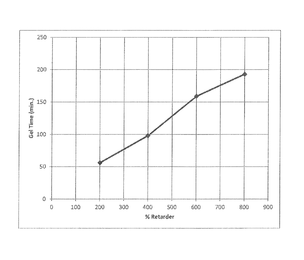
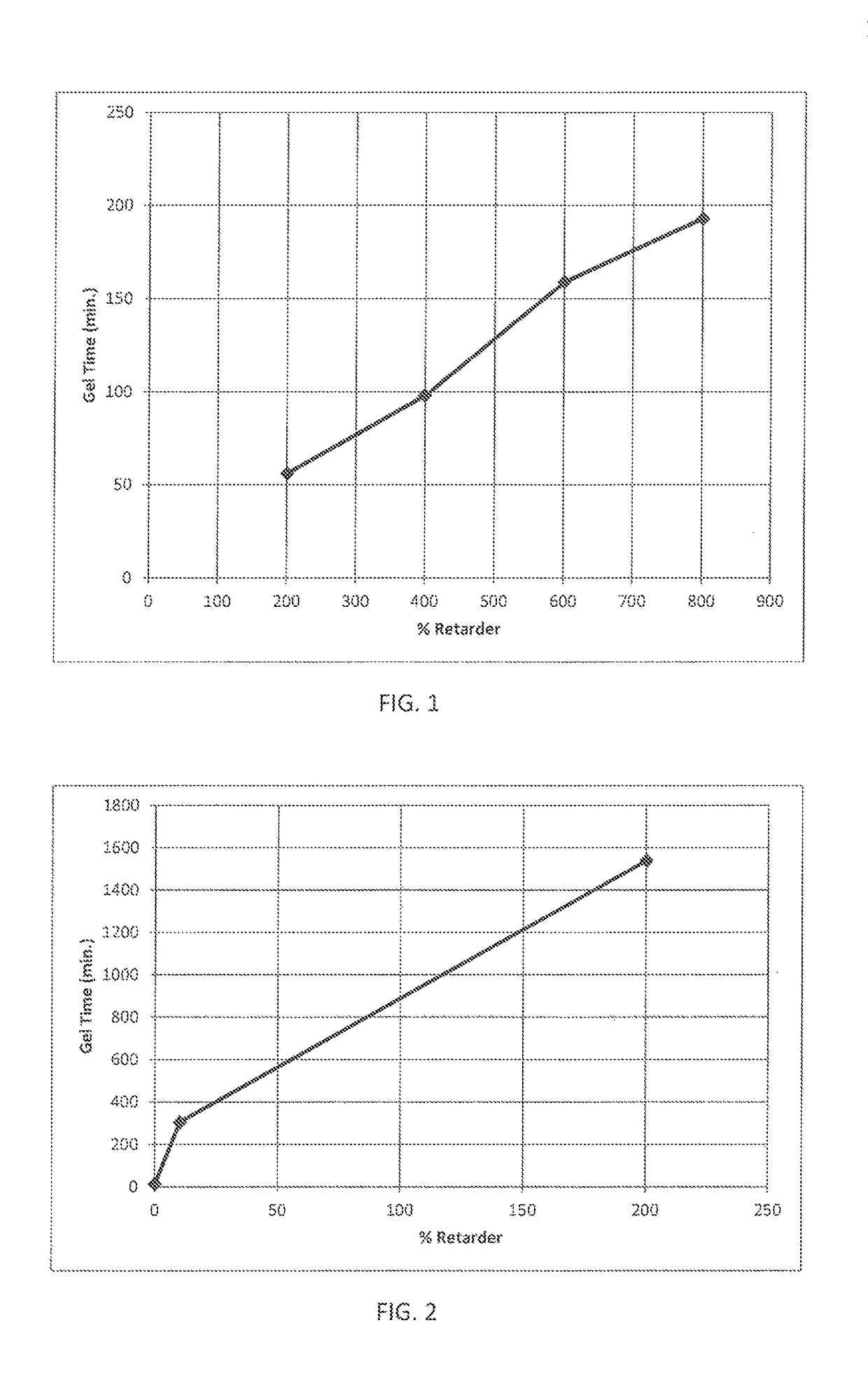
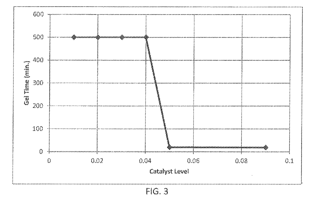
[0120]The compositions were evaluated for gel time as follows: the Gel time was determined by using a GARDCO GT-SHP “Hot Pot” Gel Timer. 100 grams of the composition was poured into an aluminum cup and placed into the “hot pot” of the gel timer that had already been stable at the cure temperature. The Gel Timer had a motor that rotated a stirrer that was inserted in the composition. As gelation cured, drag eventually exceeded torque and the motor stalled. The time at which the motor stalled is the reported Gel time in Tables I—below.

[0121]

TABLE IEx. 1Ex. 2Ex. 3Ex. 4Ex. 5Isocyanate AIsocyanate BIsocyanate C39.7939.639.4139.4139.76Isocyanate DIsocyanate EIsocyanate F59.6959.4159.1159.1159.64Isocyanate GDefoamer ADefoamer B0.50.50.490.490.5Catalyst ACatalyst BCatalystretarderCatalyst C0.990.1InhibitorCatalyst D0.1Catalyst E0.5Catalyst F0.02Plasticize...


PUM

PropertyMeasurementUnit
temperatureaaaaaaaaaa
timeaaaaaaaaaa
temperaturesaaaaaaaaaa

Abstract

The present invention provides an oil or gas wellbore polymeric cement comprising the reaction product of an aliphatic isocyanate, a trimerization catalyst, and a catalyst retarder, wherein the reaction occurs in the wellbore at a temperature of at least 250° F. (121° C.). Also provided is a method of reducing fluid loss from an oil or gas well, comprising producing a polyisocyanurate cement by combining an aliphatic isocyanate, a trimerization catalyst, and a catalyst retarder within a wellbore at a temperature of at least 250° F. (121° C.). The various embodiments of the invention meet the controllability and minimized toxicity needed for this application. Standard aliphatic polyisocyanates reduce handling concerns while providing the reactivity response that fits this temperature range.

Description

FIELD OF THE INVENTION[0001]The present invention relates in general to oil and gas drilling and more specifically to preventing the loss of drilling fluid during the creation of an oil or gas well by providing a solid polymer plug made from polyisocyanurate plastic at a well temperature range of above 250° F. (121° C.).BACKGROUND OF THE INVENTION[0002]The recovery of resources, such as natural gas or oil, from underground formations typically entails drilling a wellbore to the formation while circulating a drilling fluid, such as a water-based or oil-based drilling mud, within the wellbore. The drilling fluid flows down through the drill pipe (sometimes called a “drill string”), exits the pipe at a location adjacent the drill bit and then flows up through an annulus formed between the outside of the pipe and the wellbore wall. Circulation of the drilling fluid lubricates the drill bit and removes cuttings from the wellbore.[0003]One problem encountered in such a resource recovery p...

Claims


Application Information

Patent Timeline
Patent Type & Authority Patents(United States)
IPC IPC(8): C09K8/00C04B24/28C09K8/44
CPCC09K8/44C04B24/282C09K8/508
Inventor ZIELINSKI, DAVID PJEFFRIES, MICHAEL K.
Owner COVESTRO LLC
Why Eureka
Try Eureka