
Method and system for low coherence interferometry

a low-coherence, optical interferometer technology, applied in the field of optical measurement devices, can solve the problems of expensive, inconvenient operation, complex arrangement of optical devices in the oct interferometric system known in the ar

Active Publication Date: 2017-11-14
NETRA SYST
View PDF6 Cites 7 Cited by
  • Summary
  • Abstract
  • Description
  • Claims
  • Application Information

AI Technical Summary

Benefits of technology

The present invention aims to provide a new and improved optical device that solves the problems of previous devices. The device is compact, affordable, and includes all the benefits of previous devices. The purpose of the invention is to overcome the disadvantages of the prior art.

Problems solved by technology

Further, OCT interferometric systems known in the art are complex in arranging optical devices, expensive and are not portable.

Method used


Image

  • Method and system for low coherence interferometry
  • Method and system for low coherence interferometry
  • Method and system for low coherence interferometry

Examples


Embodiment Construction

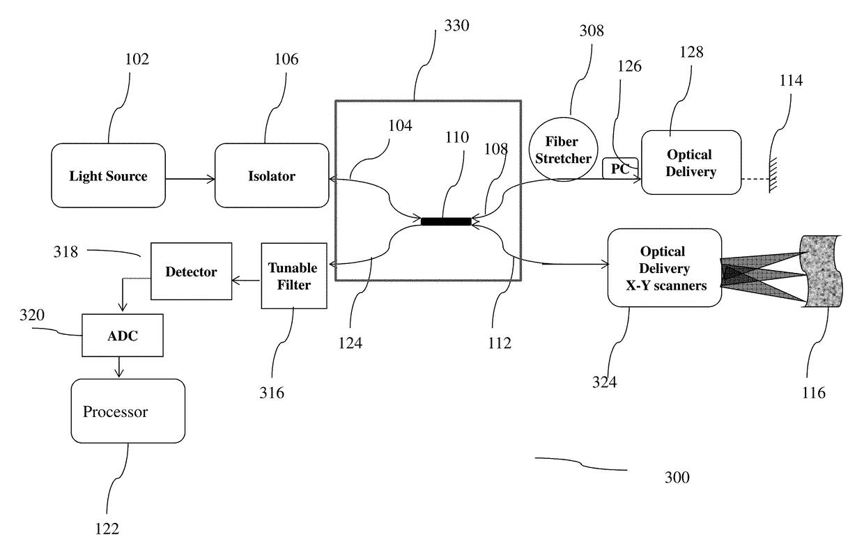
[0020]The present invention proposes an interferometric system for optical imaging, which is one of the major needs for refractive surgery, ophthalmic applications, corneal imaging, retinal imaging, endoscopic / catheter imaging, dental imaging etc. In particular, the invention is an integrated system for detection, ranging, metrology and multi-dimensional imaging.

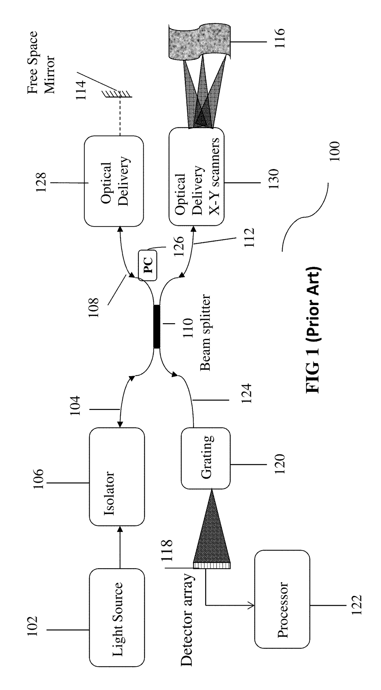
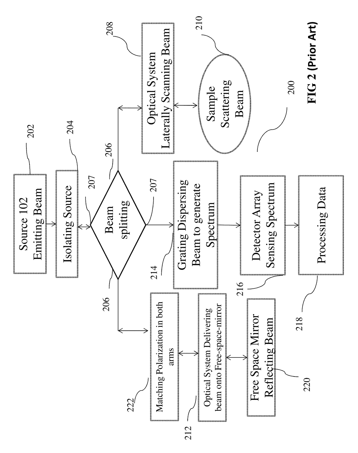
[0021]FIG. 1 illustrates a schematic figure of a Michelson Interferometric optical coherence tomography system (100) as known in the art. The interferometer (100) has a light source (102) operating at a suitable center wavelength and a suitable bandwidth. Some light sources may be sensitive to light reflected back from the interferometer. In order to protect such light sources, an optional isolator (106) may be used. The isolator absorbs the light received from the fiber optic beam splitter (110), and it stops the light from entering the source 102. In the interferometer, the source light is separated into the sample and ref...


PUM

PropertyMeasurementUnit
line-widthaaaaaaaaaa
reflectanceaaaaaaaaaa
insertion lossaaaaaaaaaa

Abstract

Optical Coherence Tomography (OCT) system and apparatus of this instant application is very useful for diagnosis and management of ophthalmic diseases such as retinal diseases and glaucoma etc. Instant innovative OCT diagnostic system leverages advancements in cross technological platforms. The Michelson interferometric system presented in this application could be used for the OCT imaging, which includes biological OCT imaging, medical OCT imaging, ophthalmic OCT imaging, corneal OCT imaging, retinal OCT imaging, and the like. A tunable filter is placed in front of the detector to make the interferometer more sensitive and accurate for examining various samples for diagnosis.

Description

REFERENCE TO CROSS RELATED APPLICATIONS[0001]The instant application is a continuation-in-part application and claims priority to the U.S. patent application Ser. No. 14 / 302,366 (filed on Jun. 11, 2014), which claims priority to now patented (U.S. Pat. No. 8,797,551) U.S. application Ser. No. 12 / 941,991 filed on Nov. 8, 2010 and U.S. application Ser. No. 13 / 723,006 filed on 20 Dec., 2012. The disclosure is hereby incorporated by this reference in its entirety for all of its teachings.FIELD OF THE INVENTION[0002]The present invention relates to the field of optical measurement devices. More particularly, the present invention relates to the field of optical test and measurement, optical ranging and imaging of a specimen using optical coherence tomography or low coherence interferometry or white-light interferometry.BACKGROUND OF THE INVENTION[0003]Optical coherence tomography (“OCT”) is a technology that allows for noninvasive, cross-sectional optical imaging in biological as well as...

Claims


Application Information

Patent Timeline
Patent Type & Authority Patents(United States)
IPC IPC(8): G01B9/02G01N21/49G01N21/47A61B3/10A61B3/107
CPCG01B9/02091A61B3/102G01B9/02027G01B9/02044G01N21/49G01N21/4795G01B2290/65A61B3/107G01B2290/35
Inventor KULKARNI, MANISH DINKARRAO
Owner NETRA SYST
Learn More