Spatial resolution enhancement in hyperspectral imaging

a hyperspectral imaging and spatial resolution technology, applied in image enhancement, optical radiation measurement, instruments, etc., can solve the problem of spatial resolution cost, achieve enhanced spatial and spectral resolution, improve signal-to-noise ratio, and enhance information

Active Publication Date: 2017-11-14
HEALTHY IO LTD
View PDF7 Cites 13 Cited by
  • Summary
  • Abstract
  • Description
  • Claims
  • Application Information

AI Technical Summary

Benefits of technology

[0008]As is well known in the art, one implementation of hyperspectral imaging substantially enhances the information that may be derived from an image by distributing a pattern of many narrow-bandpass filters over the individual pixels of an array sensor. Hyperspectral imaging provides various improvements over other imaging techniques, including: (1) enhanced spatial and spectral resolution by image dither akin to the saccadic behavior of the human eye, (2) improved signal-to-noise ratio by using more than one spectral distribution of illuminant, (3) optimized spatial distribution of individual pixel filters according to specifically designed criteria, and (4) exploitation of inelastic scatter by using one or more narrow-band illuminants. In all cases, the processing of several sequential images can partially restore the loss of spatial resolution implicit in using detector array overlaid by a fixed-mask of a large number of individual narrow-bandpass hyperspectral filters. The fourth process, i.e., (4) above, also enhances the sensitivity to individual inelastic scattering properties of the observed material or scene by using a narrow-band illuminant that is transmitted by none or only one of the hyperspectral bands. Any changes in scattered wavelength by, for example, induced fluorescence or Raman scattering, then appear with improved contrast against a dark field, potentially identifying certain biological features and some physical and / or chemical properties of structures within the field of view.
[0009]For a conventional imaging device with pixilated array of CMOS, CCD, or Foveon x3® type detector elements (hereinafter “Foveon model”), each pixel detector element ideally has the same spectral sensitivity, reducing the post processing necessary to compensate for nonuniformity of sensitivity over the image recovered from the serial data stream typically available from such an array. Foevon model detectors are available from Foveon, Inc. of San Jose, Calif., USA 95134 (see, e.g., U.S. Pat. No. 8,351,696). “Foveon x3” is a registered trademark in the U.S. Pat. Nos. 2,694,153 and 2,696,784 of Foveon, Inc. of San Jose, Calif., USA 95134.
[0010]In the first two cases, the CMOS and CCD sensing elements yield a single signal intensity output from each pixel. In the case of the Foveon model, which is a 3 dimensional pixel array, the output of each pixel consists of three outputs for the colors red, green and blue, each of which is the average over a spectrally sensitive range typically analogous and roughly equivalent to the response of the human eye. The widely available CMOS and CCD devices often have a spectral filter mask array, such as the standard Bayer mask with a rectangular or square grid of red, green and blue filters, as shown in FIGS. 1A and 1B and further discussed below, with one filter type per sensing pixel. Processing the image permits the derivation of color information in the scene, by knowing which element of the data stream is derived from which color in a way that is analogous to the simplest aspect of color vision in certain living organisms. The Bayer mask may also use CMY or GMYG rather than RGB fixed color filters, and it is this potential for diversity that led to the present invention extended to us a wide range of narrow spectral filters. In one implementation of a device for multispectral and especially hyperspectral imaging, each pixel is preceded by its own relatively narrow-band filter. While this dramatically enhances spectral resolution it carries a cost in spatial resolution, which may be wholly or partially recovered by the presently-invented system and methods described below.

Problems solved by technology

While this dramatically enhances spectral resolution it carries a cost in spatial resolution, which may be wholly or partially recovered by the presently-invented system and methods described below.

Method used


Image

  • Spatial resolution enhancement in hyperspectral imaging
  • Spatial resolution enhancement in hyperspectral imaging
  • Spatial resolution enhancement in hyperspectral imaging

Examples


Embodiment Construction

[0050]In the above summary, and the following detailed description, reference is made to FIGS. 1-6. This application incorporates by reference the disclosure of international application no. PCT / US13 / 23813, titled “Hyperspectral Imaging Systems, Units, And Methods”, filed on Jan. 30, 2013.

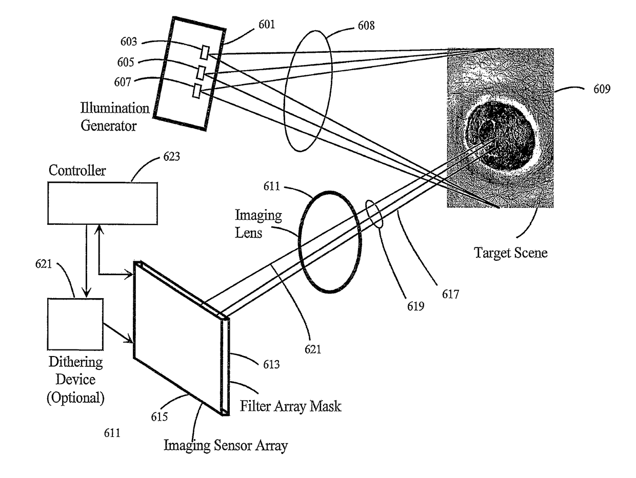
[0051]In one preferred and non-limiting embodiment, the system comprises a hyperspectral sensor array where each elementary pixel sensor is preceded by its own narrow-band filter, upon which is imaged an area of interest on or in a body in question by an optical system with adequate capabilities over the required spectrum, and a number of sequentially available illuminators, which may include broad-band sources of different spectral distributions and / or narrow-band illuminants such as lasers or light emitting diodes. FIG. 3 shows five possible illuminant spectral distributions I(λ), where each may be varied, for example the narrow band source may be anywhere within, or for some types of fluorescenc...


PUM


Abstract

In a hyperspectral imaging system and method, a pixilated imaging sensor array receives light reflected from, transmitted through, or scattered by a target scene. Images of the target scene are acquired at a number of times and these images are processed to generate hyperspectral data for each pixel of the imaging sensor array based on data for the pixel included in each of the acquired images. This processing can include spatially aligning two or more of the images that were spatially shifted with respect to each other when acquired based on at least one common image feature in the images.

Description

CROSS REFERENCE TO RELATED APPLICATION[0001]This patent application claims the benefit of international patent application number PCT / US13 / 23711, titled SPATIAL RESOLUTION ENHANCEMENT IN HYPERSPECTRAL IMAGING, filed on Jan. 30, 2013. International patent application number PCT / US13 / 23711 claims the benefit of U.S. Provisional Patent Application No. 61 / 592,187, filed Jan. 30, 2012, which is incorporated herein by reference.BACKGROUND OF THE INVENTION[0002]Field of the Invention[0003]This invention relates to the fields of medical diagnostics, telemedicine, mobile health, wireless health, and any application of hyperspectral imaging based upon a mask of individual pixel filters.[0004]Description of Related Art[0005]Hyperspectral imaging is an imaging modality that gathers continuous information across a vast portion of the electromagnetic spectrum, as opposed to traditional imaging modalities (e.g., a conventional digital otoscope (such as the digital otoscope shown and described in U...

Claims


Application Information

Patent Timeline
Patent Type & Authority Patents(United States)
IPC IPC(8): G06T7/00H04N5/232G01J3/36G01J3/28G01J3/51G06T7/33
CPCG06T7/337G01J3/2823G01J3/36H04N5/23229G01J3/51G06T2207/30088G06T2207/10152H04N23/80
Inventor SMART, ANTHONY
Owner HEALTHY IO LTD
Why Eureka
Try Eureka