
Cyclone vacuum cleaner and cyclone separation device

a vacuum cleaner and cyclone technology, applied in the direction of vacuum cleaners, reversed direction vortex, domestic applications, etc., can solve the problems of vacuum cleaners and noise, and achieve the effect of preventing injuries when handling

Active Publication Date: 2017-11-21
VERSUNI HLDG BV
View PDF16 Cites 1 Cited by
  • Summary
  • Abstract
  • Description
  • Claims
  • Application Information

AI Technical Summary

Benefits of technology

The present invention aims to reduce noise in vacuum cleaners and separation devices by eliminating or minimizing a further noise source. It also aims to maintain the device's ability to effectively separate dirt from air. This is achieved through the use of a cyclone chamber, a dirt collecting chamber, a dirt-duct for directing dirt particles from the cyclone chamber to the dirt collecting chamber, and an air-guide adjacent to the dirt-duct for reducing the air's momentum. These features work together to improve the efficiency and performance of the vacuum cleaner or separation device.

Problems solved by technology

A commonly known problem in the field of cyclone vacuum cleaners is noise caused by the whirling air stream in the aforementioned air discharging pipe.

Method used


Image

  • Cyclone vacuum cleaner and cyclone separation device
  • Cyclone vacuum cleaner and cyclone separation device
  • Cyclone vacuum cleaner and cyclone separation device

Examples


Embodiment Construction

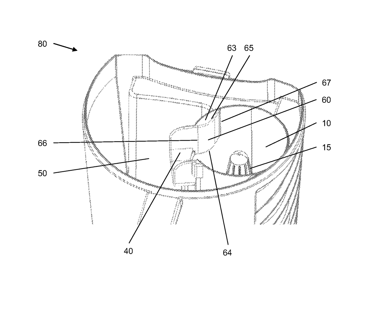
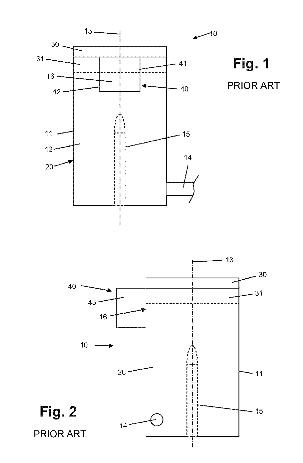
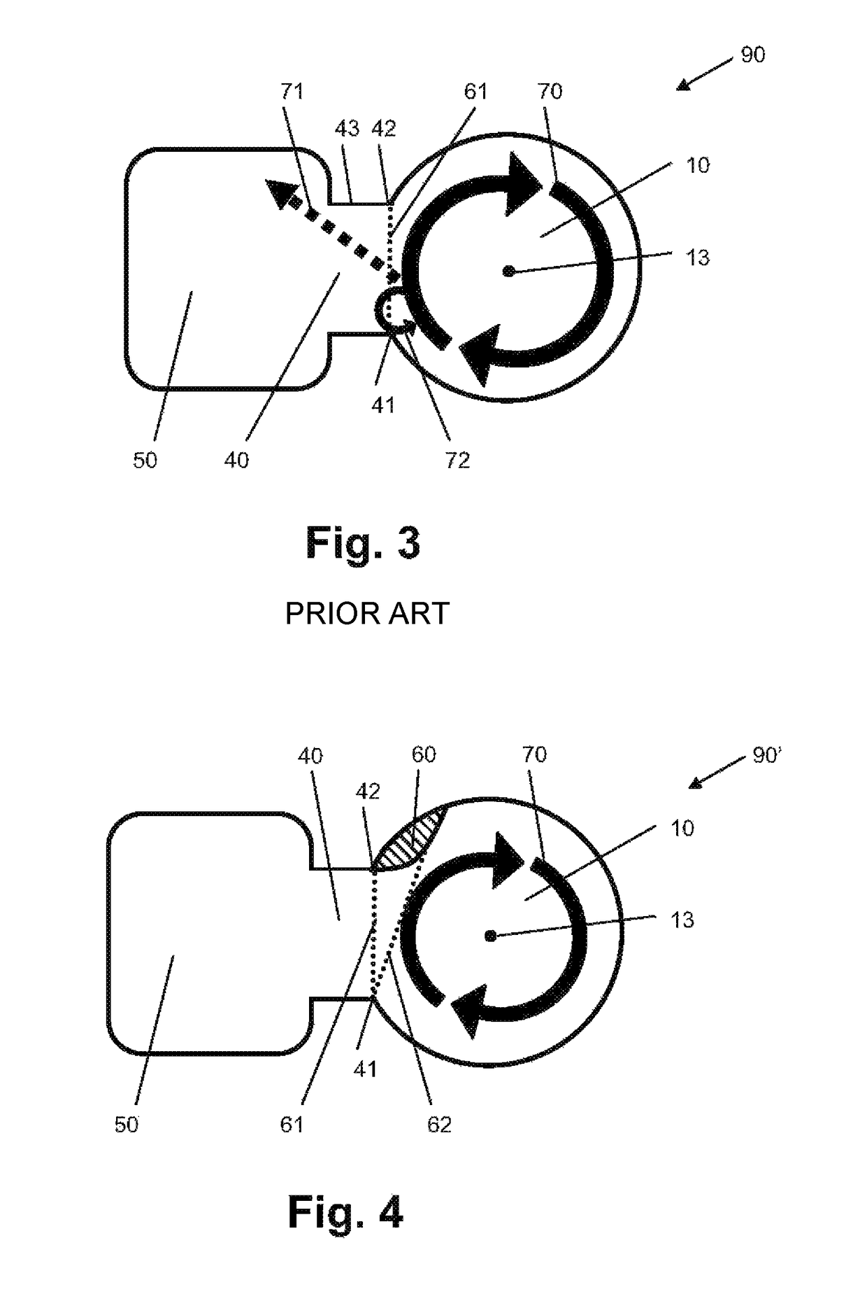
[0029]FIGS. 1 and 2 show a cyclone chamber 10 of a cyclone separating device according to prior art. The device serves for separating particles from air, and is intended to be used in a vacuum cleaner, particularly a so-called bagless vacuum cleaner, in which the separation process takes place by letting a sucked-in mixture of air and dirt particles perform a rotational vortex or cyclone movement, wherein the dirt particles can be collected at the outside of the cyclone. Air as the medium transporting the dirt particles rotates so fast that the air looses grip of the dust. Particles are forced away from the center by centrifugal force. Dirt separation occurs, when the centrifugal force is stronger than the component of the drag force of air which is pointing towards the center of the separator where the air is sucked out. Typical particles include plant pollen, human and animal hair, textile fibers, paper fibers, outdoor soil, water droplets, mud and human skin cells, in general all...


PUM


Abstract

The present invention relates to a cyclone separation device for separating particles from air and a cyclone vacuum cleaner (80). It has the objective to reduce noise without impairing the dirt separation performance. This is achieved an arrangement comprising a cyclone chamber (10), a dirt collecting chamber (50) arranged adjacent to the cyclone chamber (10) for collecting dirt particles separated from air, a dirt-duct (40) between the cyclone chamber (10) and the dirt collecting chamber (50) for allowing dirt particles to pass from the cyclone chamber (10) towards the dirt collecting chamber (50), and an air-guide (60) arranged adjacent to the dirt-duct (40) for reducing the momentum of the air in the dirt-duct (40).

Description

[0001]This application is the U.S. National Phase application under 35 U.S.C. §371 of International Application No. PCT / IB2012 / 057369, filed on Dec. 17, 2012, which claims the benefit of U.S. Provisional Application No. 61 / 577,387 filed on Dec. 19, 2011. These applications are hereby incorporated by reference herein.FIELD OF THE INVENTION[0002]The present invention relates to a cyclone vacuum cleaner and a cyclone separation device for separating particles from air.BACKGROUND OF THE INVENTION[0003]In general, a vacuum cleaner comprises a suction nozzle to be moved along a surface to be cleaned, and a motor for generating a suction force which is used for removing particles, typically dust and dirt particles, from the surface and displacing these particles to the inside of the vacuum cleaner. A device is arranged inside the vacuum cleaner for separating the particles from the air. As a result of a separation process, the dust can be collected in a suitable space, and clean air can be...

Claims


Application Information

Patent Timeline
Patent Type & Authority Patents(United States)
IPC IPC(8): A47L9/16A47L9/00B04C5/14B04C5/185
CPCA47L9/1608A47L9/0081B04C5/185B04C5/14A47L9/1658
Inventor VAN DER KOOI, JOHANNES TSEARDVAN DEN BOSCH, MICHAELDAM, PETER
Owner VERSUNI HLDG BV
Learn More