
Steerable sheath including elastomeric member

a technology of elastomeric member and sheath, which is applied in the direction of magnetic variable regulation, instruments, catheters, etc., can solve the problems of high current density in the tissue, and patient safety risks, etc., to achieve minimize resistance, and quick inflation and deflation

Active Publication Date: 2017-11-21
IMRICOR MEDICAL SYST
View PDF118 Cites 4 Cited by
  • Summary
  • Abstract
  • Description
  • Claims
  • Application Information

AI Technical Summary

Benefits of technology

[0014]In a further aspect of the invention, the steerable sheath shaft comprises a reinforced polymer tube in which the reinforcing material is non-metallic based (Kevlar, PEEK, Nylon, fabric, polyimide, etc.) or a hybrid of metallic and non-metallic materials and the reinforcing geometry may comprise a braid, a coil, or a slit tube that mimics a coil and combinations of the foregoing. In yet another aspect of the invention, the reinforced polymer tube may also be segmented with varying flexibility along its length to provide the user with the ability to deflect the catheter in a region in which the segment is more flexible than other segments.
[0023]In another aspect of the invention, the lumen(s) used to fill the elastomeric member(s) have a diameter sufficient to allow for the injection of viscous fluids into the elastomeric member and allow for quick inflation and deflation of the elastomeric member.
[0024]In another aspect of the invention, the lumen(s) used to fill the elastomeric member are coated to minimize resistance between the lumen wall and liquid within the lumen and allow for quick inflation and deflation of the elastomeric member.
[0025]In another aspect of the invention, the elastomeric member is made sufficiently pliable to allow it to inflate with viscous fluid without requiring excessive pressure at the injection site or within the lumen used to fill the elastomeric member.

Problems solved by technology

Each of the three fields associated with MRI presents safety risks to patients when a medical device is in close proximity to or in contact either externally or internally with patient tissue.
One important safety risk is the heating that may result from an interaction between the RF field of the MRI scanner and the medical device (RF-induced heating), especially medical devices that have elongated conductive structures, such as braiding and pull-wires in catheters and sheaths.
The RF-induced heating safety risk associated with elongated metallic structures in the MRI environment results from a coupling between the RF field and the metallic structure.
RF currents induced in the metallic structure may be delivered into the tissue, resulting in a high current density in the tissue and associated Joule or Ohmic tissue heating.
Also, RF induced currents in the metallic structure may result in increased local specific absorption of RF energy in nearby tissue, thus increasing the tissue's temperature.
In addition, RF induced currents in the metallic structure may cause Ohmic heating in the structure, itself, and the resultant heat may transfer to the patient.
The static field of the MRI will cause magnetically induced displacement torque on any device containing ferromagnetic materials and has the potential to cause unwanted device movement.
Conventional steerable sheaths are not designed for the MRI and may cause image artifacts and / or distortion that significantly reduce image quality.

Method used


Image

  • Steerable sheath including elastomeric member
  • Steerable sheath including elastomeric member
  • Steerable sheath including elastomeric member

Examples


Embodiment Construction

[0059]Numerous structural variations of an MR compatible steerable elastomeric member sheath in accordance with the invention are contemplated and within the intended scope of the invention. Those of skill in the art will appreciate that the exemplary steerable elastomeric member sheath may be coupled to other types of steerable sheath shafts having control handles. Therefore, for purposes of discussion and not limitation, an exemplary embodiment of the MR compatible steerable elastomeric member sheath will be described in detail below.

[0060]Referring to the FIGS. like elements have been numbered with like reference numerals.

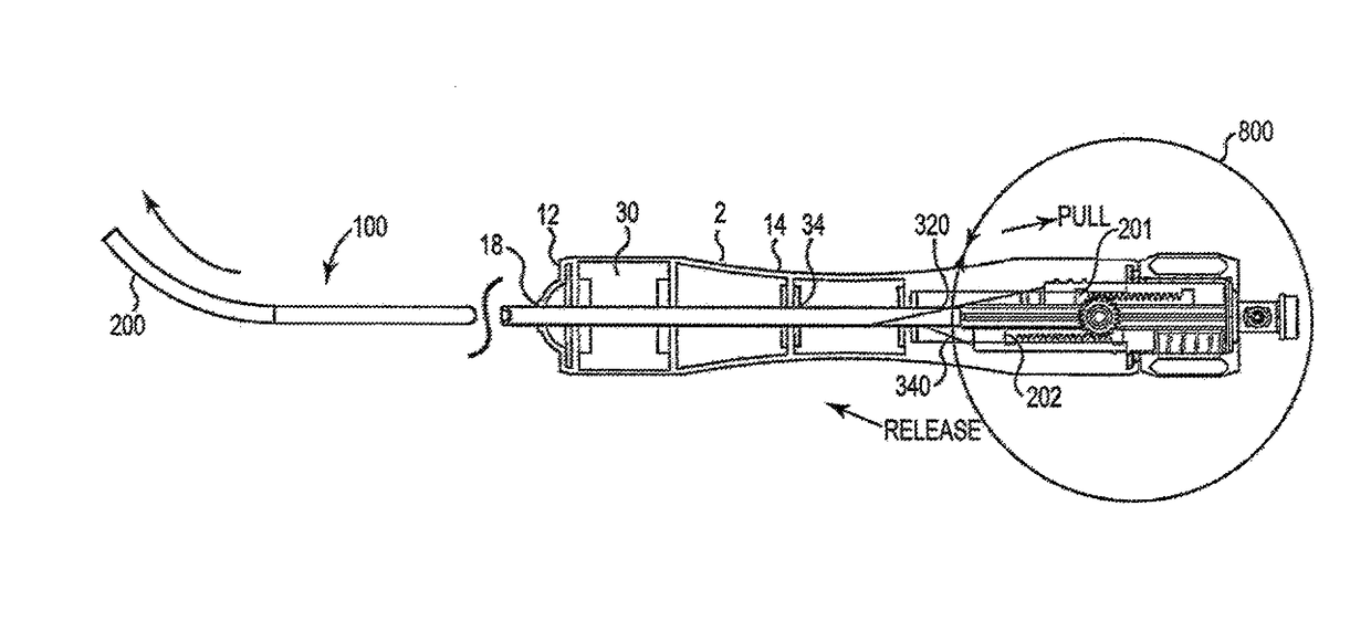
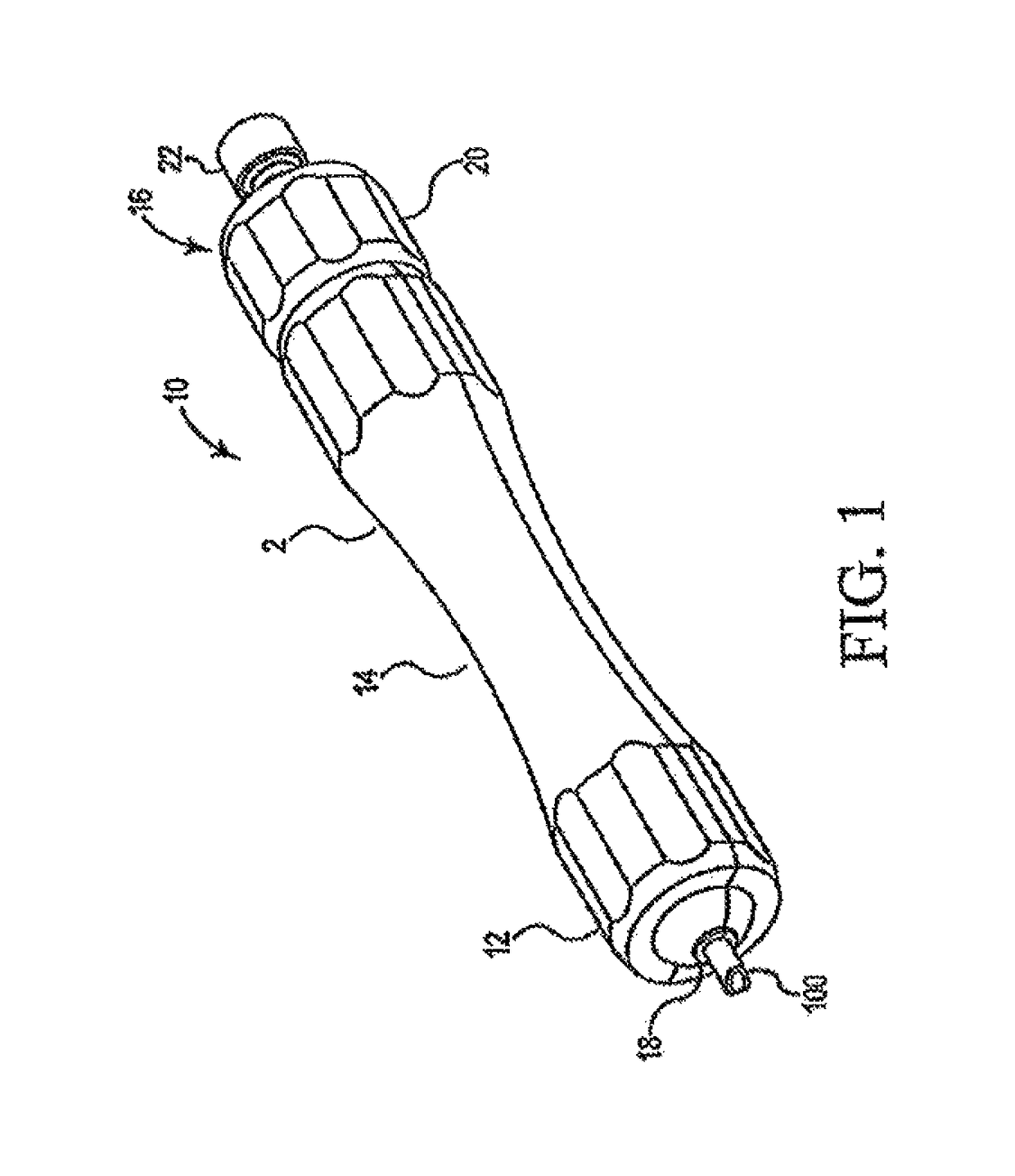
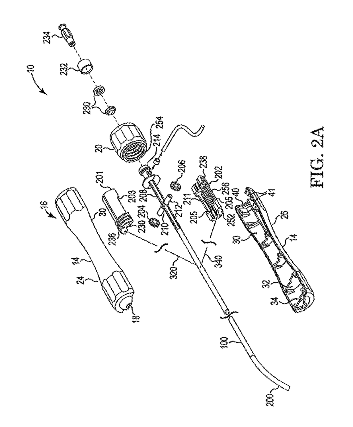
[0061]Referring now to FIG. 1, the control handle 10 in accordance with the invention includes a cover 2 as illustrated in FIG. 1. Cover 2 includes distal portion 12, hand-graspable middle region 14, and proximal end 16. Distal portion 12 includes aperture 18 through which steerable sheath shaft 100 exits. Proximal end 16 includes rotatable adjustment knob 20 an...


PUM


Abstract

An MR compatible steerable sheath with elastomeric member is provided. The elastomeric member is configured to serve as a reservoir and receive contrast media therewithin. The elastomeric member is positioned on the distal end of the steerable sheath and may circumferentially surround the sheath shaft or be offset from a longitudinal axis thereof. In operation, the contrast media allows a user to view the distal tip of the steerable sheath by virtue of the contrast media contained within the elastomeric member.

Description

CROSS REFERENCE TO RELATED APPLICATIONS[0001]This application is a continuation of PCT patent application Serial No.: PCT / US2015 / 051910, filed on Sep. 24, 2015; which claims the benefit of priority to U.S. Provisional patent application Ser. No. 62 / 054,723, filed on Sep. 24, 2014; and this application is also a continuation-in-part of U.S. patent application Ser. No. 14 / 705,617, filed on May 6, 2015; which is a continuation of U.S. application Ser. No. 14 / 106,177, filed on Dec. 13, 2013, now U.S. Pat. No. 9,138,561, issued Sep. 22, 2015; which is a continuation-in-part of U.S. application Ser. No. 13 / 819,981, filed on (§371 date) Jan. 20, 2014, (abandoned); which claims the benefit of PCT application Serial No.: PCT / US2012 / 069487, filed on Dec. 13, 2012; which claims the benefit of U.S. Provisional application Ser. No. 61 / 576,161, filed on Dec. 15, 2011; and U.S. application Ser. No. 14 / 106,177 is a continuation application of PCT application Serial No.: PCT / US2013 / 074331, filed on ...

Claims


Application Information

Patent Timeline
Patent Type & Authority Patents(United States)
IPC IPC(8): A61M25/01G01R33/28A61B5/055A61M25/00
CPCA61M25/0127A61M25/0136A61M25/0147G01R33/286A61M25/0054A61M25/0108A61M25/0052
Inventor KIMMEL, SCOTTPAGE, DOUGLAS A.
Owner IMRICOR MEDICAL SYST
Learn More