Cushioning slides

a technology of cushioning and slides, which is applied in the direction of rotary machine parts, mechanical machines/dredgers, domestic applications, etc., can solve the problems of increasing the cost of repair and replacement of various parts of the apparatus, affecting the economics of impacting operations, and requiring additional costs, so as to improve the impacting performance, reduce noise and maintenance costs, and improve the effect of impacting performan

Active Publication Date: 2017-11-21
TERMINATOR IP
View PDF15 Cites 9 Cited by
  • Summary
  • Abstract
  • Description
  • Claims
  • Application Information

AI Technical Summary

Benefits of technology

[0027]The present invention is particularly suited for use with a mechanical impact hammer and to further reduce prolixity, the present invention will herein be described with respect to use with same.
[0163]In contrast, the use of the aforementioned cushioning slide allows the weight to be manufactured to rough tolerances, or even rough cast or forged before accurately machining a relatively small part of the weight sides for placement of the cushioning slides. Any discrepancy in the necessary width of the weight can be accommodated simply be adjusting the thickness of the cushioning slide, typically via adjustment of the first layer.

Problems solved by technology

The effects of both the physical shock and the noise generated during impacts can have significant adverse effects on the economics of impacting operations.
The machinery apparatus must be manufactured with sufficient structural strength to withstand the repetitive impacts, whilst repairs and replacements of various parts of the apparatus are required over time due to ongoing wear and tear.
The additional costs of both these issues are overheads on the cost efficiencies of operating the apparatus.
Furthermore, legislation, health, safety and environmental requirements in many countries now impose restrictions on the noise levels and time periods that such impacting apparatus may be operated.
The inherent characteristics of breaking apparatus such as highly repetitive cyclical operations, high velocities of the descending weight, large shock loads that can be transferred to the apparatus, variation in properties of impact surface, angle of impact and so forth, create challenges for any material used to provide low friction interfaces between the moving surfaces of the apparatus, while having sufficient resilience to accommodate the shock loads.
However, in many applications, particularly rock-breaking applications, wet lubricants cannot be used as the dust generated during operation will adhere to the lubricant and result in a higher-friction and abrasive interface, and dry lubricants do not always perform well on mating surfaces with low contact areas and high pressures such as rock breaker guide columns.

Method used


Image

  • Cushioning slides
  • Cushioning slides
  • Cushioning slides

Examples


Embodiment Construction

[0202]

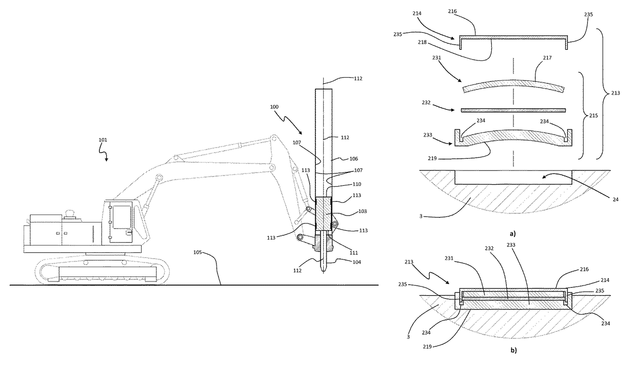
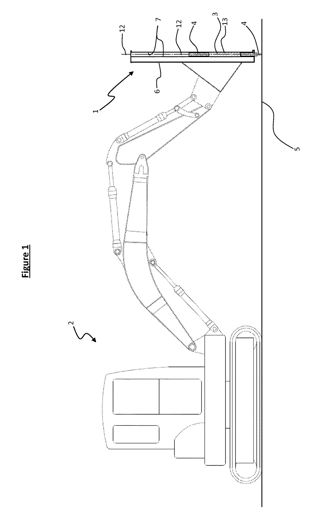
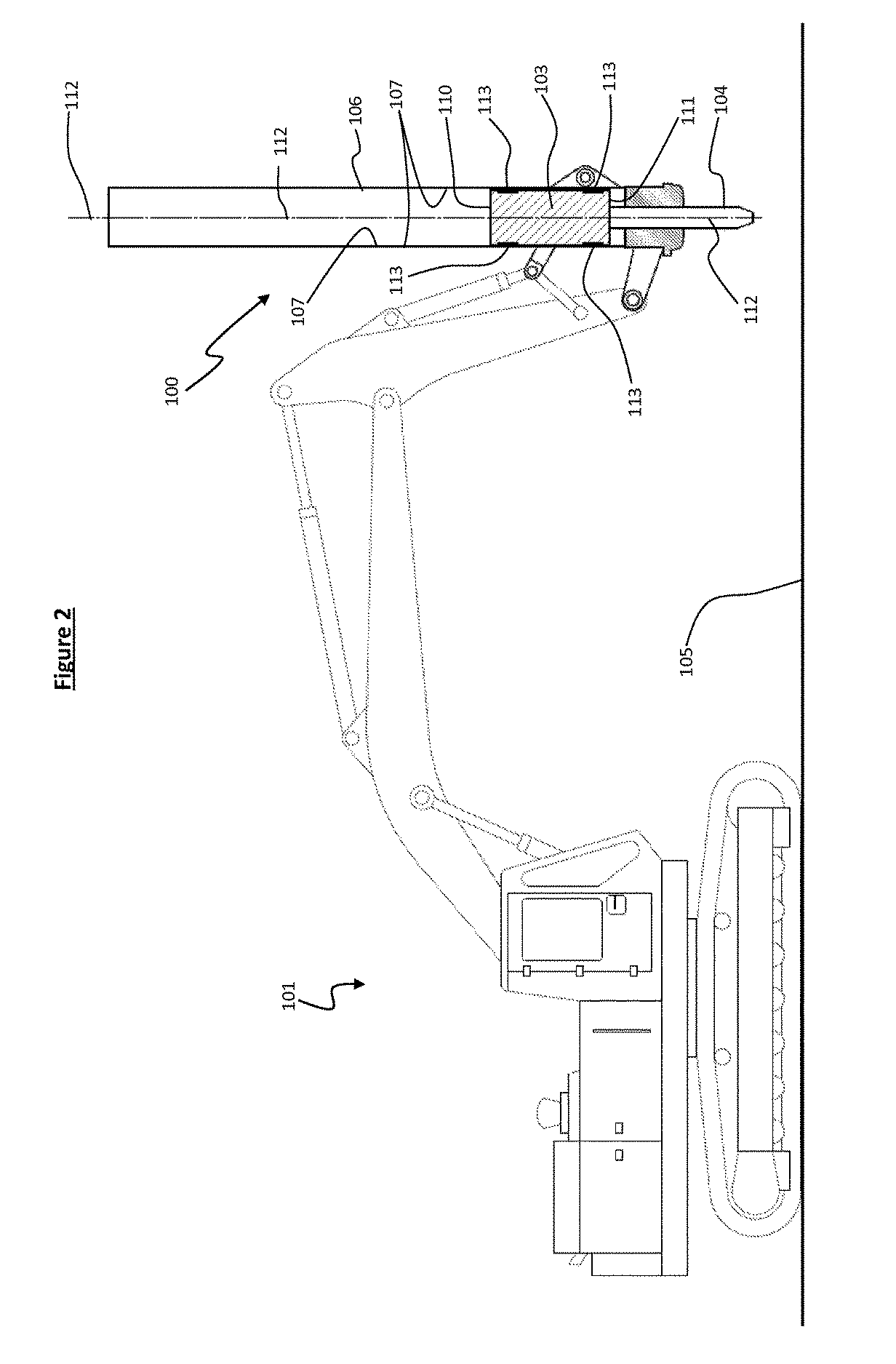
Reference numerals for FIGS. 1-19 (1) - impact hammer (2) - small excavator (3) - hammer weight (4) - tool end (5) - working surface (6) - housing (7) - housing inner side walls (8) - wide side walls (9) - narrow side walls (10) - upper distal face (11) - lower distal face (12) - impact axis (13) - cushioning slides (14) - first layer (15) - second layer (15a-d) - second layer (16) - exterior surface - first layer (17) - outer surface - second layer (17a-d) - outer surface - second layer (18) - underside - first layer (19) - interior surface -second layer (19a-d) - interior surface -second layer (20) - longitudinal apices (21) - weight surface under second layer (22) - displacement void (22a-d) - displacement void (23a-23e) - securing feature (23f-23k) - securing feature (23m) - securing feature (24) - socket (25) - retention face (26) - location projections (27) - locating recesses (28) - aperture - second layer (29) - aperture - first layer (30) - locating portion(101) - lar...


PUM

PropertyMeasurementUnit
surface roughness Raaaaaaaaaaa
compressive strengthaaaaaaaaaa

Abstract

An apparatus (1) with a reciprocating component (3) fitted with composite cushioning slides (13) on an exterior surface (8, 9). The reciprocating component (3) is movable along a reciprocation path and the composite cushioning slide (13) includes an exterior first layer (14) and an interior second layer (15). The first layer (14) is formed with an exterior surface (16) configured and orientated to come into sliding contact with a containment surface (7) of the apparatus (1) during the reciprocating movement of the reciprocating component (3), the first layer (14) is formed from a material of predetermined friction and / or abrasion resistance properties. The interior second layer (15) is located between the first layer (14) and reciprocating component (3) and is formed from a shock-absorbing material having predetermined shock absorbing properties.

Description

CROSS-REFERENCE TO OTHER APPLICATIONS[0001]This is a National Phase of International Application No. PCT / IB2013 / 055909 filed on Jul. 18, 2013, which claims priority from New Zealand Patent Application No. 601317, filed on Jul. 18, 2012.TECHNICAL FIELD[0002]The present invention relates to a means for providing cushioning slides for machinery including moving parts in mutually sliding and / or impacting contact, and in particular, to impact hammers, drop hammers and other breaking apparatus in which impact power is derived from reciprocating a mass.BACKGROUND ART[0003]Machinery such as rock breakers, impact hammers, drop hammers and the like apply significant impact forces to both the working surface being impacted and the machinery itself. The impact forces generate both a kinetic impulse and an audio shockwave, the magnitude and origin of which is dependent on numerous factors including the:[0004]machinery size,[0005]mass and velocity of the impacting weight,[0006]construction of the...

Claims


Application Information

Patent Timeline
Patent Type & Authority Patents(United States)
IPC IPC(8): B25D17/24E21B1/02F16C29/02F16C29/00B32B27/40B32B27/32B32B27/28B32B27/08B32B7/02B32B15/095B32B15/18E02F3/96B25D17/00B32B7/022
CPCB25D17/24B32B15/095B32B15/18B32B27/08B32B27/288B32B27/32B32B27/40E21B1/02F16C29/002F16C29/02B32B7/02F16C2300/28B25D17/00B25D2222/42B25D2222/57B25D2222/61B32B2307/538B32B2307/56B32B2475/00E02F3/966F16C2202/04F16C2202/06F16C2204/60F16C2208/10F16C2240/12F16C2240/26B32B7/022
Inventor ROBSON, ANGUS PETER
Owner TERMINATOR IP
Why Eureka
Try Eureka