Hydraulic fracturing system and method

a technology of hydraulic fracturing and hydraulic fracturing, which is applied in the direction of separation process, lighting and heating equipment, and wellbore/well accessories, etc., can solve the problems of low production rate, mediocre quality results, and high cost per barrel

Active Publication Date: 2017-12-12
LARSON KEVIN
View PDF32 Cites 131 Cited by
  • Summary
  • Abstract
  • Description
  • Claims
  • Application Information

AI Technical Summary

Problems solved by technology

Many methods have been developed but all have drawbacks to some degree; high cost per barrel, mediocre quality outcomes, low production rates.
The existing technology for the treatment and / or disposal of FBW / PW is extremely expensive and is not environmentally friendly.
The current practice causes damage to the public's infrastructure from mass transportation of FBW / PW from the drill site and fresh water to the site, damage to the environment from spills and contamination, and earthquakes from FBW / PW being disposed of in injection wells.
All the transporting of both fresh water and FBW / PW adds carbon footprint and greenhouse gases.
The practice of driving a fracturing pump with a transmission has inherent drawbacks; sudden load applications, up-shifting problems, horsepower losses through the transmission resulting in more fuel consumption, flow degradation due to less than optimal pump speeds and over torque possibilities in low gears damaging equipment.
These items cause a large footprint on a small space and lend to a very dangerous work environment.
The open rigs cause over burdening noise levels to the public also.
Some recycling systems are too slow processing low volumes of water and consuming more energy across the board.
Some methods render usable low quality water but fluctuations in salinity and chemicals create hardships treating water for re-use.
Other methods clean the water well but are left with larger amounts of waste such as dirty filters still needing processed or disposed of.
Utilizing a transmission the pump flow is marginalized as the transmission has horse power losses through itself and is not an exact match for maximizing the speed and flow from the pump.
This is an additional expense, another contractor and equipment on the drill site and more energy is consumed.
Disposal at permitted facilities is very expensive, requires trucking and separate from the fracturing process.
Utilizing a transmission to drive a fracturing pump causes quick hard loading of the engine resulting in killing the engine when coming on line against a high pressure manifold potentially causing damage to all components.
Pump sets are traditionally open frame mounted and leaks can be strewn on the ground easily from the engine, transmission and the fracturing pump itself.
Open units also cause a very high ambient noise level on the drill site and surrounding environment.

Method used


Image

  • Hydraulic fracturing system and method
  • Hydraulic fracturing system and method
  • Hydraulic fracturing system and method

Examples


Embodiment Construction

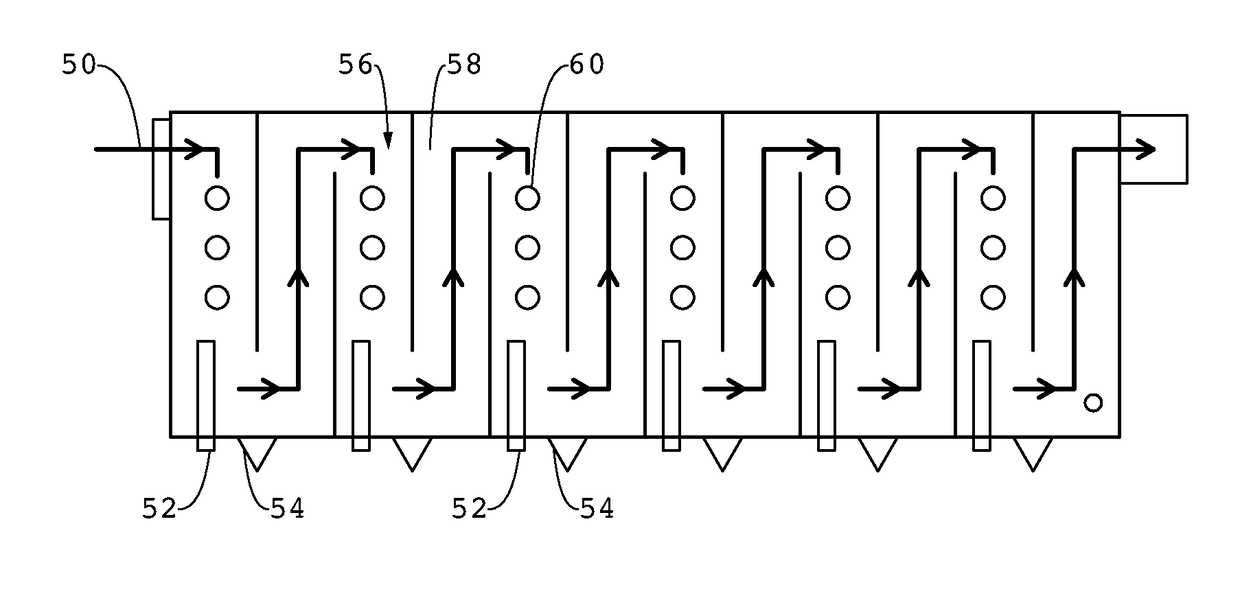
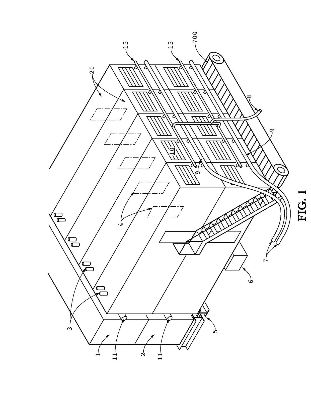
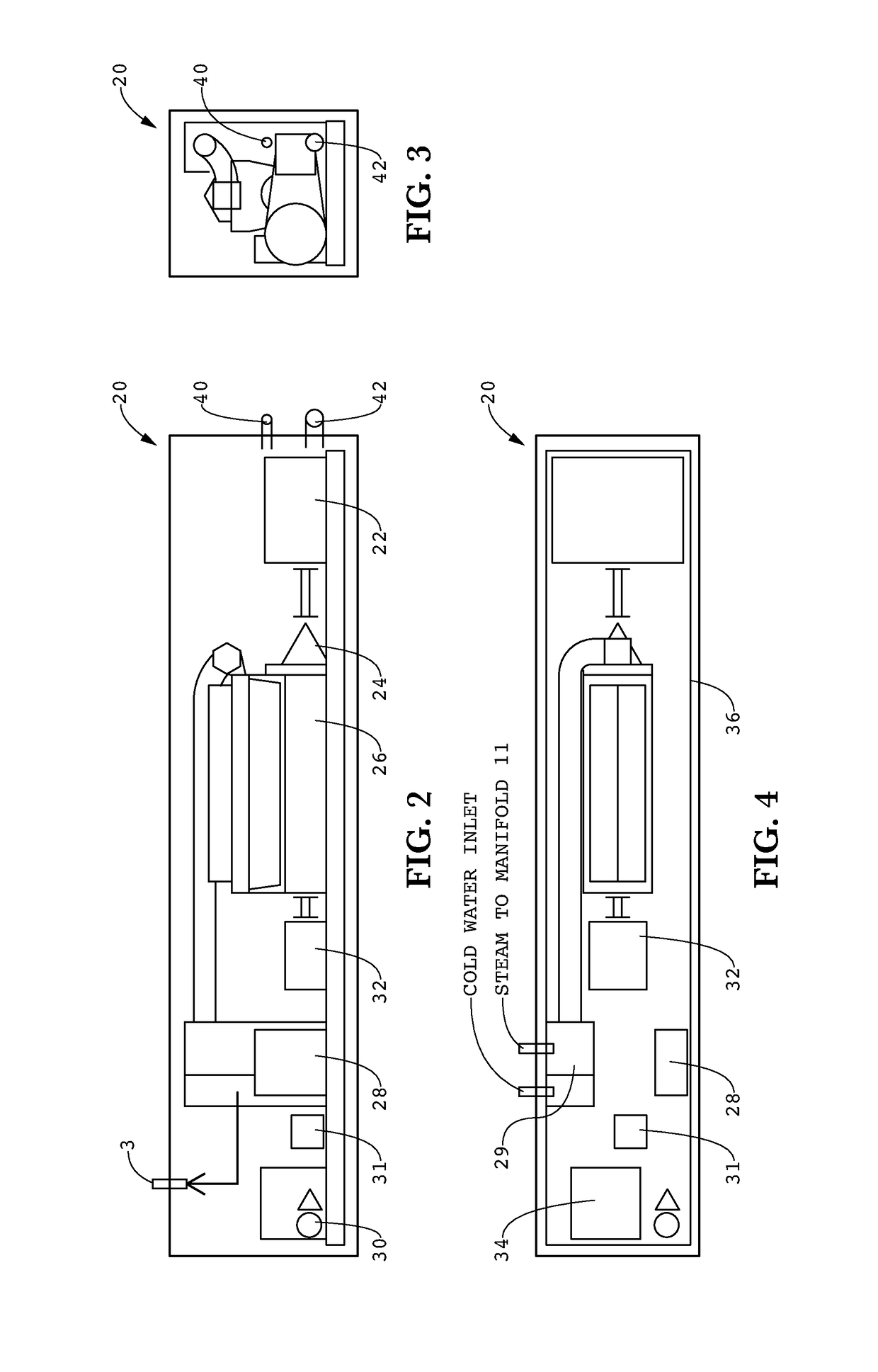
[0009]Exemplary embodiments provide a fracturing unit for hydraulic fracturing having an engine and a fracturing pump connected to the engine through a variable speed torque converter. Exemplary embodiments also provide a hydraulic fracturing system using multiple fracturing units which are sized similar to ISO containers. A hydraulic fracturing system may also force flow back water, produced water, or fresh water through a heat exchanger so that heat from the fracturing engines can be transferred to these liquids in order to vaporize them. A force cooled fractioning unit then can accept the vapor / steam in order to condense the various components and produce distilled water for re-use in the fracturing process or for release into the environment.

[0010]The foregoing and other features and advantages of the present invention will be apparent from the following more detailed description of the particular embodiments, as illustrated in the accompanying drawings.

BRIEF DESCRIPTION OF THE ...


PUM

PropertyMeasurementUnit
pressureaaaaaaaaaa
temperatureaaaaaaaaaa
flow rateaaaaaaaaaa

Abstract

Disclosed herein is a fracturing unit for hydraulic fracturing having an engine and a fracturing pump connected to the engine through a variable speed torque converter. Also disclosed is a hydraulic fracturing system using multiple fracturing units which are sized similar to ISO containers. A hydraulic fracturing system may also force flow back water, produced water, or fresh water through a heat exchanger so that heat from the fracturing engines can be transferred to these liquids in order to vaporize them. A force cooled fractioning unit then can accept the vapor / steam in order to condense the various components and produce distilled water for re-use in the fracturing process or for release into the environment.

Description

CROSS-REFERENCE TO RELATED APPLICATIONS[0001]This application claims priority to U.S. application Ser. No 61 / 616,312 filed on Mar. 27, 2012 and is herein incorporated by reference in its entirety.TECHNICAL FIELD[0002]Embodiments generally relate to systems and method related to hydraulic fracturing, specifically those that increase efficiency, and recycle the FBW and / or PW.BACKGROUND OF THE ART[0003]The process of hydraulic fracturing oil and gas wells produces industrial wastes referred to as Flow-back Water (FBW initial return) and Produced Water (PW long term return). Millions of gallons of regurgitated FBW / PW, per drill site, contain chemicals and other contaminates brought to the surface of the earth which need to be rendered harmless and disposed of. The O&G industry is searching for new ways to minimize the usage of Fresh Water (FW) being withdrawn from the environment which has increased the interest in recycling of the waste waters. Many methods have been developed but all ...

Claims


Application Information

Patent Timeline
Patent Type & Authority Patents(United States)
IPC IPC(8): E21B43/34F28B1/02E21B43/40B01D5/00F28B1/00F28D7/16E21B43/26F28D21/00E21B43/24
CPCE21B43/26E21B43/40F28B1/02F28D7/1623F28D21/001E21B43/34Y10T137/6579B01D5/006B01D5/009B01D5/0009B01D5/0036B01D5/0081E21B43/2405F28B1/00F28D2021/0059E21B43/2607E21B43/35
Inventor LARSON, KEVIN
Owner LARSON KEVIN
Why Eureka
Try Eureka