
Life of a semiconductor by reducing temperature changes therein via reactive power

a technology of reactive power and semiconductor, which is applied in the direction of power conversion systems, electrical equipment, ac network circuit arrangements, etc., can solve the problems of increased heat generation, more losses, and increased heat production, and achieve accurate identification of temperature changes, increase the useful life of the semiconductor, and facilitate the effect of reducing the temperature change in the semiconductor

Active Publication Date: 2018-01-02
GE ENERGY POWER CONVERSION TECH
View PDF29 Cites 5 Cited by
  • Summary
  • Abstract
  • Description
  • Claims
  • Application Information

AI Technical Summary

Benefits of technology

The patent text describes a technology to prevent the heat loss of an IGBT (insulated gate bipolar transistor) in a converter system, by circulating reactive power within the system to maintain a constant current. This helps to reduce temperature changes in the semiconductor and increase its useful life. The technology also includes a peak detector to accurately identify temperature changes and a controller to alter the maximum temperature for improved performance.

Problems solved by technology

Transitioning each IGBT from the on-state to the off-state and vice versa results in heat production, as power is dissipated within each IGBT during switching events.
The higher the current being switched on or off, the more losses, therefore the more heat.
As current increases, the conduction losses within each IGBT also increase.
Just as the power from renewable energy sources can often vary throughout a day, so can losses dissipated in the IGBTs.
The thermal cycling, which may occur over minutes or hours, can result in mechanical stress and increased rates of IGBT failure over time due to material fatigue.
Thermal cycles, specifically in the baseplate and the bond wire of the switch, among others factors, results in device fatigue.
This approach, however, does not prevent cracks from expanding to critical sizes, for example, which can ultimately lead to fractures.

Method used


Image

  • Life of a semiconductor by reducing temperature changes therein via reactive power
  • Life of a semiconductor by reducing temperature changes therein via reactive power
  • Life of a semiconductor by reducing temperature changes therein via reactive power

Examples


Embodiment Construction

[0008]Given the aforementioned deficiencies, a need exists for systems and methods that prolong the life of a semiconductor by preventing crack formations due to drastic temperature changes during switching.

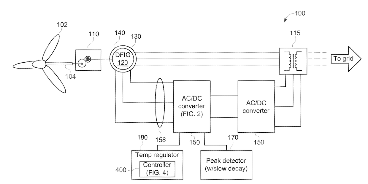
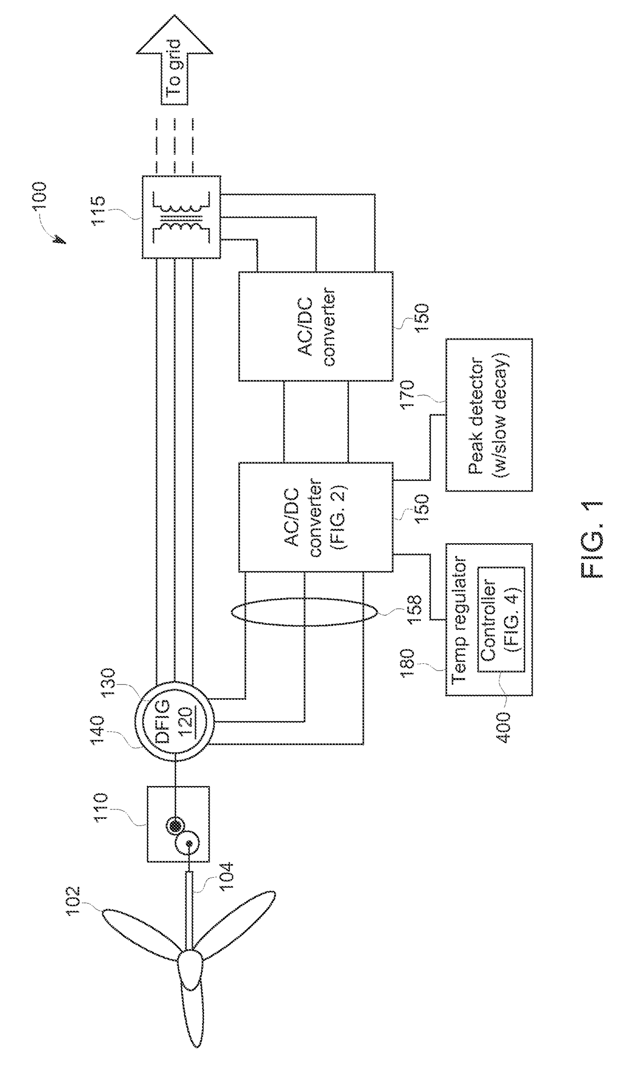
[0009]In the present technology, to keep IGBT heat losses from dropping in proportion to reductions in renewable power production, the converter may circulate reactive power within the system such that the net reactive power to or from the grid is unaffected but the current within an IGBT bridge is held more constant. Circulating reactive power keeps current magnitude from dropping in proportion to power. Specifically, the converters operate at a reduced power factor than without circulation of reactive power. A doubly fed induction generator (DFIG) has a topology configured to feed reactive power to the grid directly from the line converter or indirectly by the rotor converter via the generator. Thus, one IGBT bridge can be controlled to output more reactive current and another ...


PUM


Abstract

Provided is a system for regulating temperature change of semiconductor components within a converter. The system includes a temperature regulator in communication with at least one semiconductor within the converter and a power source, the temperature regulator comprising a controller. Also included is a peak detector in communication with at least one of the semiconductors and configured to identify a maximum temperature of each semiconductor when the semiconductor conducts high current.

Description

I. FIELD OF INVENTION[0001]The present invention relates generally to extending the useful life of a power semiconductor. More specifically, the present invention relates to extending the useful life of a semiconductor when operating as an electronic switch in renewable energy applications.II. BACKGROUND OF THE INVENTION[0002]Renewable energy, harvested from natural phenomena such as sunlight and wind, has replaced conventional fuels in areas of energy service and power generation. Electrical power devices, such as semiconductors, convert energy obtained from renewable energy sources, such as solar power and wind power, from dc or variable frequency ac to utility (grid) frequency. Conversion is generally achieved by switching a plurality of semiconductors on and off at high frequency to synthesize sine wave voltages via pulse width modulation (PWM) techniques.[0003]Three-terminal semiconductors, such as insulated-gate bipolar transistor (IGBTs), metal-oxide-semiconductor field-effec...

Claims


Application Information

Patent Timeline
Patent Type & Authority Patents(United States)
IPC IPC(8): H02M1/42H02M1/32H02M7/537
CPCH02M1/4208H02M7/537H02M1/32H02J3/383H02J3/386H02J3/50Y02E10/56
Inventor WAGONER, ROBERT GREGORYSMITH, DAVID
Owner GE ENERGY POWER CONVERSION TECH
Learn More