Low thermal mass joint

a low-temperature mass, support joint technology, applied in the direction of machines/engines, climate sustainability, sustainable transportation, etc., can solve the problems of shortening the effective lifespan of the joint, affecting the efficiency of the joint, so as to prevent the movement of the combustor circumferentially

Active Publication Date: 2018-01-23
RTX CORP
View PDF11 Cites 2 Cited by
  • Summary
  • Abstract
  • Description
  • Claims
  • Application Information

AI Technical Summary

Benefits of technology

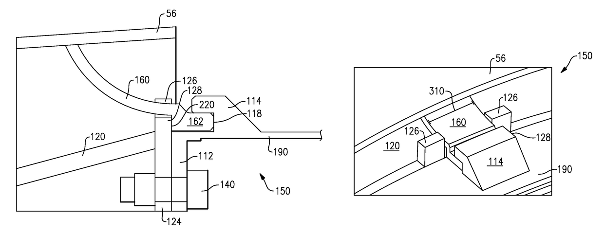
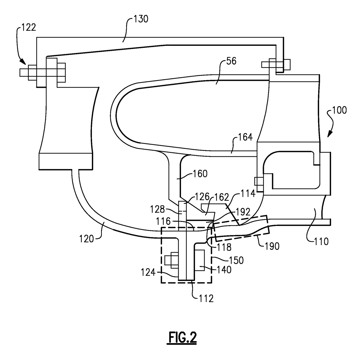
[0009]In a further embodiment of the foregoing gas turbine engine, the diffuser case further includes at least one diffuser tab at each of the at least one low thermal mass joints, and the at least one diffuser tab contacts a corresponding support finger of the combustor, thereby preventing circumferential movement of the combustor.

Problems solved by technology

Some sections of the turbine engine, such as a turbine on-board injector (TOBI) system, run extremely hot during operation.
When one component of a joint is very hot, relative to the temperature at the joint, the large thermal mass of the joint causes significant amounts of heat cycling in the arm connecting the hotter component to the joint.
The heat cycling in turn weakens the material of the arm, thereby shortening the effective lifespan of the joint.
In such engines it is difficult to isolate the joints from each other, resulting in joints having a large thermal mass.

Method used


Image

  • Low thermal mass joint
  • Low thermal mass joint
  • Low thermal mass joint

Examples


Embodiment Construction

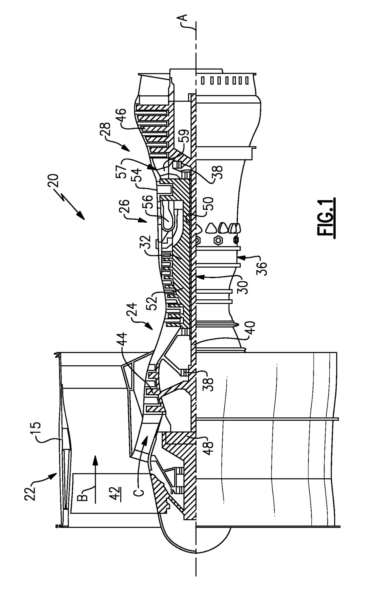
[0030]FIG. 1 schematically illustrates a gas turbine engine 20. The gas turbine engine 20 is disclosed herein as a two-spool turbofan that generally incorporates a fan section 22, a compressor section 24, a combustor section 26 and a turbine section 28. Alternative engines might include an augmentor section (not shown) among other systems or features. The fan section 22 drives air along a bypass flow path B in a bypass duct defined within a nacelle 15, while the compressor section 24 drives air along a core flow path C for compression and communication into the combustor section 26 then expansion through the turbine section 28. Although depicted as a two-spool turbofan gas turbine engine in the disclosed non-limiting embodiment, it should be understood that the concepts described herein are not limited to use with two-spool turbofans as the teachings may be applied to other types of turbine engines including three-spool architectures.

[0031]The exemplary engine 20 generally includes ...


PUM


Abstract

A gas turbine engine includes a tangential on-board injector (TOBI) fluidly connected to a compressor section. A diffuser case structurally supports a combustor section and the tangential on-board injector via at least one low thermal mass joint.

Description

CROSS-REFERENCE TO RELATED APPLICATION[0001]This application claims priority to U.S. Provisional Application No. 61 / 874,440 filed Sep. 6, 2013.STATEMENT REGARDING FEDERALLY SPONSORED RESEARCH OR DEVELOPMENT[0002]This invention was made with government support under Contract No. FA8650-09-D-2923-0021 awarded by the United States Air Force. The Government has certain rights in this invention.BACKGROUND OF THE INVENTION[0003]The present disclosure relates generally to turbine engine support structures and more specifically to a low thermal mass support joint for the same.[0004]Gas turbine engines for aircraft include multiple turbine engine sections that operate cooperatively to generate thrust and propel the aircraft forward. The turbine engine sections are maintained in position by a turbine engine superstructure including a diffuser case. In typical examples, the diffuser case is connected to multiple engine components at a single joint via a flange and fastener arrangement.[0005]So...

Claims


Application Information

Patent Timeline
Patent Type & Authority Patents(United States)
IPC IPC(8): F01D25/24F01D9/04F01D25/08
CPCF01D25/243F01D25/246Y02T50/671F01D25/08F01D9/041Y02T50/60
Inventor STEVENS, MICHAEL S.BLANEY, KEN F.
Owner RTX CORP
Why Eureka
Try Eureka