Pnuematic system for an aircraft

a pneumatic system and aircraft technology, applied in the direction of machines/engines, transportation and packaging, machine/engines, etc., can solve the problems of excessive thrust specific fuel consumption (sfc), limited minimum thrust that can be achieved by the engine in flight (known as “flight idle thrust”), and current systems are not optimal

Active Publication Date: 2018-01-30
ROLLS ROYCE PLC
View PDF17 Cites 13 Cited by
  • Summary
  • Abstract
  • Description
  • Claims
  • Application Information

AI Technical Summary

Benefits of technology

[0014]Accordingly, the invention provides a pneumatic system for an aircraft in which energy from an offtake that would normally be wasted is used to provide additional compression for a lower pressure core engine offtake. Consequently, the lower pressure engine offtake air may be taken from a lower pressure stage of the compressor compared to prior arrangements, thereby reducing the energy required to compress the lower pressure offtake air, thereby resulting in decreased engine SFC. Furthermore, the addition of a turbine downstream of the high pressure engine core offtake reduces the pressure and temperature of the air dumped overboard. This in turn provides the advantage of reducing stressing of the exhaust structure, and also reducing noise from the handling bleed valves in view of the lower temperature and pressure exhaust efflux.
[0018]The second core compressor offtake may comprise a cabin bleed offtake. The second core compressor offtake may be in fluid communication with an aircraft environmental control system downstream of the turbocompressor air compressor. The pneumatic system may comprise a plurality of second core compressor offtakes. For example, the pneumatic system may comprise a high pressure cabin bleed offtake in fluid communication with a relatively high pressure core compressor stage of the gas turbine engine, and a low pressure cabin bleed offtake in fluid communication with a relatively low pressure core compressor stage of the gas turbine engine. Advantageously, the engine handling bleed, which is normally “dumped overboard” (i.e. the gas flows into a low pressure sink such as the bypass duct), can be used to increase the pressure of the cabin bleed, thereby reducing the pressure required at the inlet of the cabin bleed offtake while still providing the necessary pressure, temperature and flow rate to operate the ECS.
[0021]Advantageously, the system provides further operability by allowing the compressor to be selectively bypassed, thereby providing additional control over the cabin bleed offtake pressure.
[0024]The pneumatic system may further comprise a core compressor offtake heat exchanger configured to exchange heat between the first and second core compressor offtake flows. The core compressor offtake heat exchanger may be located downstream of the turbocompressor air compressor and air turbine. Advantageously, the gas temperatures of the cabin offtake and engine handling offtake flows can be somewhat normalised. Consequently, the temperature of the cabin bleed air can be lowered before being passed to the ECS, thereby potentially decreasing the amount of cooling required in the ECS.
[0029]Where the handling bleed modulation valve is operable in further positions between the open and closed positions, the method may comprise determining a cabin bleed offtake pressure, and, where the cabin bleed offtake pressure is above a predetermined value, operating the respective valve to open the cabin bleed offtake and, where the cabin bleed offtake pressure is below the predetermined value, operating the handling bleed modulation valve such that the cabin bleed flow pressure downstream of the turbocompressor air compressor is above the predetermined value. Advantageously, where the cabin bleed flow pressure downstream of the compressor is insufficient (i.e. below the predetermined value), the system can operate the handling bleed valve to drive the turbine of the turbocompressor, thereby driving the air compressor of the turbocompressor to increase the cabin bleed flow pressure downstream of the turbocompressor air compressor until the pressure reaches the predetermined value. Consequently, the invention ensures that the pressure provided downstream of the turbocompressor air compressor is above the required value during a relatively wide range of operating conditions, without the requirement for operating a higher pressure cabin bleed flow, which might otherwise result in increased SFC.

Problems solved by technology

However, current systems are non-optimal, in the sense that relatively high pressure cabin bleed air must be used to provide sufficient pressure and flow to the ECS at some engine conditions, such as when the engine is at low power.
Such arrangements are relatively complex, and may result in excessive thrust specific fuel consumption (SFC), since the cabin bleed air must be provided at relatively high pressure in such prior arrangements.
In some cases, the minimum thrust that can be achieved by the engine in flight (known as “flight idle thrust”) is limited by the overall pressure ratio required to operate the ECS system.
A further disadvantage of current systems, is that the high pressure handling bleed air is simply vented to the bypass duct, and therefore largely lost to the thermodynamic cycle of the engine, save for a small amount of thrust generated by the bleed air.
In an unrelated problem, aircraft gas turbine engines are a major source of aircraft noise.
A major source of engine noise during low power operation of a gas turbine engine (i.e. during approach and landing) is the efflux from the handling bleed valve.
The high levels of noise are thought to be caused by the high pressure, high temperature air turbulently mixing in the engine bypass flow.

Method used


Image

  • Pnuematic system for an aircraft
  • Pnuematic system for an aircraft
  • Pnuematic system for an aircraft

Examples


Embodiment Construction

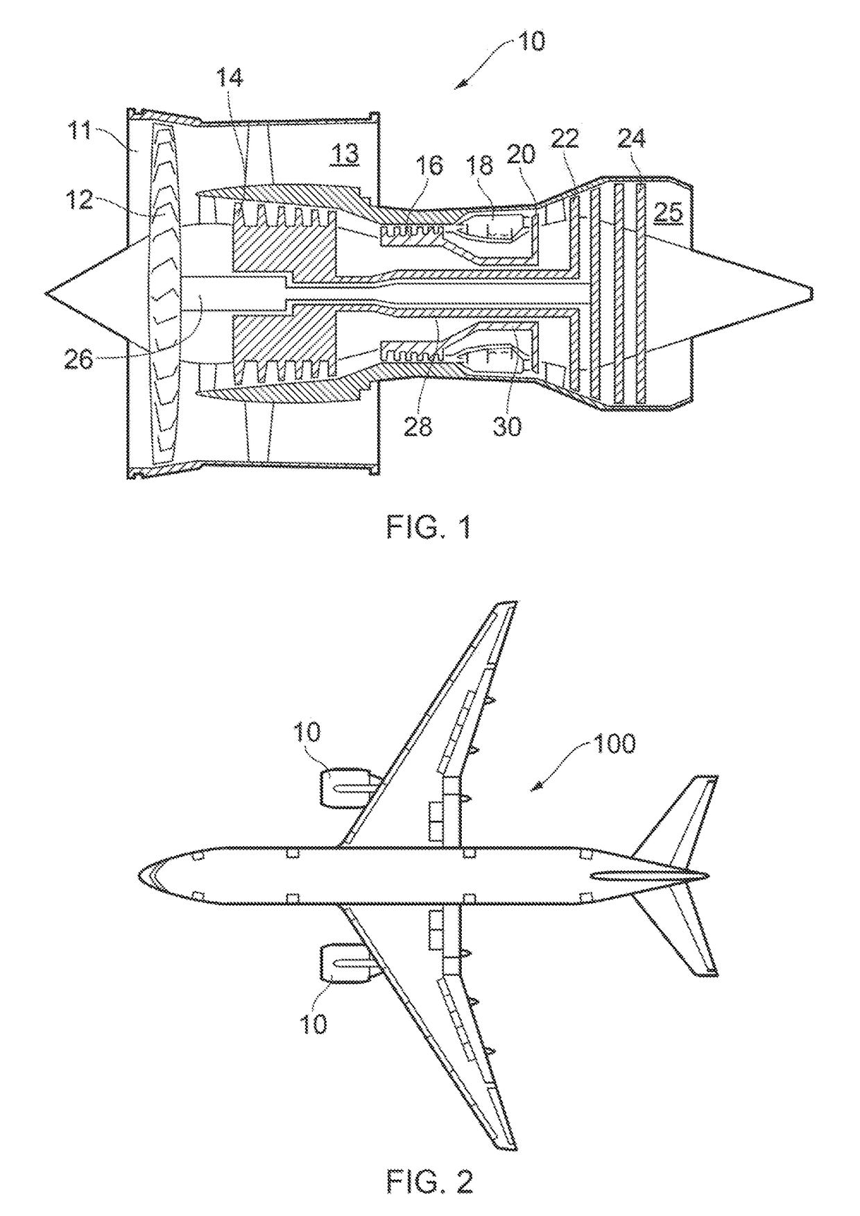
[0040]FIG. 1 shows a gas turbine engine 10. Gas turbine engines 10 are mounted on an aircraft 100 in pairs, as shown in FIG. 2. The engine 10 comprises, in axial flow series, an air intake duct 11, an intake fan 12, a bypass duct 13, an intermediate pressure (IP) compressor 14, a high pressure (HP) compressor 16, a combustor 18, a high pressure turbine 20, an intermediate pressure turbine 22, a low pressure turbine 24 and an exhaust nozzle 25. The fan 12, compressors 14, 16 and turbines 20, 22, 24 all rotate about the major axis of the gas turbine engine 10 and so define the axial direction of gas turbine engine.

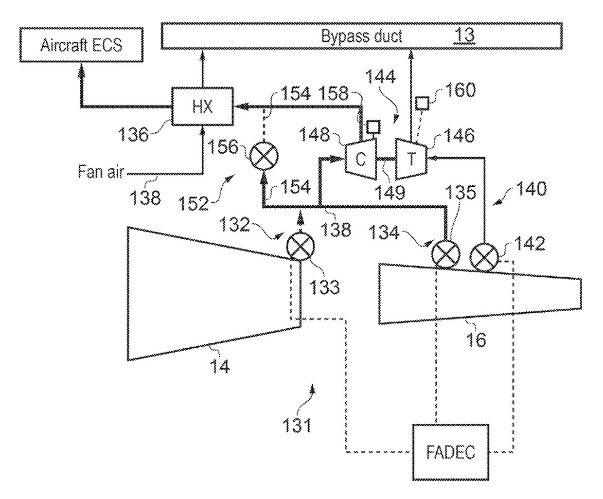
[0041]FIG. 4 shows a pneumatic system 131 for use with the gas turbine engines 10 and aircraft 100. The pneumatic system 131 comprises at least one first engine core compressor bleed offtake in the form of an engine handling bleed offtake 140. An intake of the offtake 140 is in fluid communication with a relatively high pressure main engine compressor stage such as a compres...


PUM


Abstract

A pneumatic system 131 for use with gas turbine engines 10 and aircraft 100. The pneumatic system 131 comprises a first engine core compressor bleed offtake in the form of an engine handling bleed offtake 140, and a second engine core compressor bleed offtake in the form of first and second cabin bleed offtake 132, 134, the handling bleed being configured to supply higher pressure air than the cabin offtakes 132, 134. The system 131 comprises a turbocompressor 144 comprising an air compressor 148 driven by a turbine 146. The handling bleed offtake 140 is in fluid communication with the turbocompressor air turbine 146 to thereby drive the air turbine 146, and the cabin bleed offtakes 132, 134 are in fluid communication with the turbocompressor air compressor 148 such that air from the offtakes 132, 134 is compressed by the turbocompressor air compressor 148.

Description

FIELD OF THE INVENTION[0001]The present invention relates to a pneumatic system for an aircraft.BACKGROUND TO THE INVENTION[0002]FIG. 1 shows a gas turbine engine 10. Gas turbine engines 10 are mounted on an aircraft 100 in pairs, as shown in FIG. 2. The engine 10 comprises, in axial flow series, an air intake duct 11, an intake fan 12, a bypass duct 13, an intermediate pressure compressor 14, a high pressure compressor 16, a combustor 18, a high pressure turbine 20, an intermediate pressure turbine 22, a low pressure turbine 24 and an exhaust nozzle 25. The fan 12, compressors 14, 16 and turbines 20, 22, 24 all rotate about the major axis of the gas turbine engine 10 and so define the axial direction of gas turbine engine.[0003]Air is drawn through the air intake duct 11 by the intake fan 12 where it is accelerated. A significant portion of the airflow is discharged through the bypass duct 13 generating a corresponding portion of the engine 10 thrust. The remainder is drawn through...

Claims


Application Information

Patent Timeline
Patent Type & Authority Patents(United States)
IPC IPC(8): F02C9/18B64D13/06F02C6/08B64D13/04B64D13/08F02K3/075
CPCF02C9/18B64D13/04B64D13/06B64D13/08F02C6/08F02K3/075Y02T50/56B64D2013/0603B64D2013/0618F05D2260/213F05D2270/101Y02T50/50
Inventor MOES, THIERRY
Owner ROLLS ROYCE PLC
Why Eureka
Try Eureka